Welcome to this tutorial on how to create a grid on a surface in Grasshopper. In this tutorial, we will be discussing which component to use and how to control the grid size. This technique can be useful for creating complex geometries and patterns in architectural design. Let’s get started!
Using the Divide Surface component to create a grid on a surface
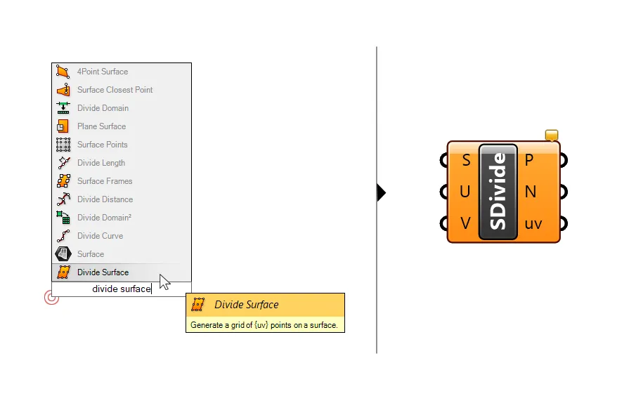
The component we’ll need to generate a grid of points on an input surface is called ‘Divide Surface‘.
To add the component to the Grasshopper canvas, double-click on an empty part of the canvas. Type ‘Divide Surface‘ into the search field and click on it.
Just like the Divide Curve component, which will generate a specified number of points on a curve for us, the Divide Surface component will generate points on the surface.
While for a curve we can specify the number of division points on the curve with a single number, we need two values when dividing a surface.
The inputs for the Divide Surface component are the Surface to divide (S), and the number of divisions in the U and V direction.
We can specify the number of divisions we want to generate on the surface grid with these two values.
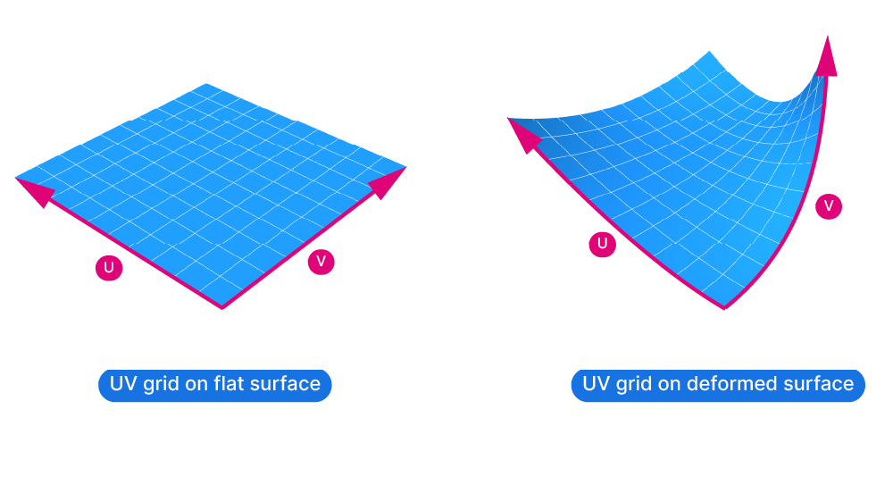
What are the U and V directions of a surface?
You can think of the U and V direction of a surface as the equivalent of a surface-specific coordinate system. Just like the X and Y axis, the U and V directions are at a right angle to each other and they describe a grid on the surface. While the X and Y axis are always straight and perpendicular to each other, the U and V directions transform and deform with the surface.
Here is the UV grid of a simple, flat surface and of a deformed surface:
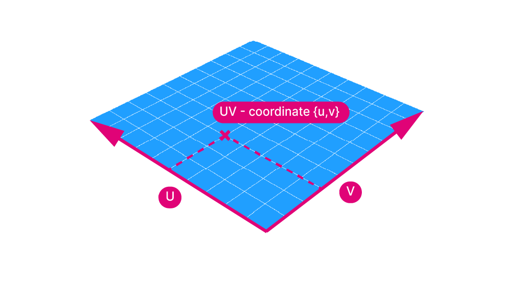
Just like curves have a start and an end point, the U and V curves of a surface also have a direction, a start and end point. This allows us to describe the location of points on the surface with UV-values.
The UV-values of a surface are very similar to the Curve Parameter values of a curve. Just like curves, the U and V directions have a number assigned to their start and endpoint. These numbers define a domain, and every point between the start and end value can be described with a value within that domain.
This means that we can describe any point on a surface, by providing a U and V value pair, called a UV-coordinate.

Reparametrizing a surface to get consistent UV domains
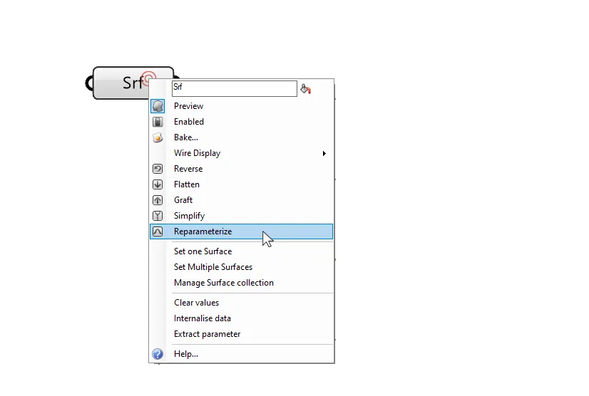
Every surface in Rhino has a domain assigned at the time of creation, but the numbers of the domains can vary greatly from surface to surface. To make locating points on a surface more consistent and predictable, we can Reparametrize the input surface.
To reparametrize a surface, right-click either on the surface component itself (as shown below) or the input (S) of any component that requires a surface. You’ll find the reparametrize option in the dropdown menu.
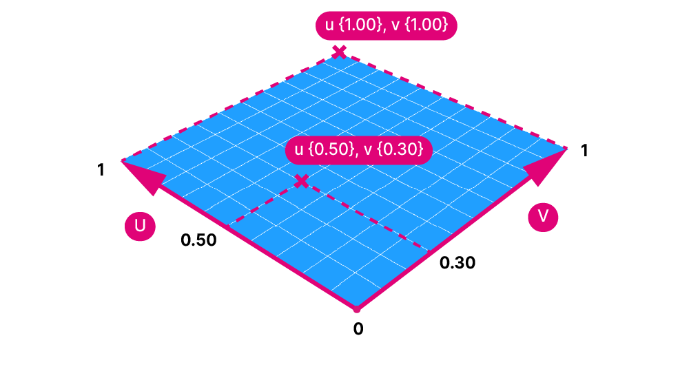
Reparametrizing a surface means that the U and V domains will both be reset to a range that goes from 0.00 at the start to 1.00 at the end. That way it’s clear that a UV coordinate of {0,0} will be at the corner, and a value of {0.50, 0.50} in the middle of the evaluated surface.
Now how does this relate to creating a grid on a surface in Grasshopper? Behind the scenes, the Divide Surface component generates unique U and V value pairs for us, all we need to do is specify the amount of divisions we want in the U and V direction. The component then directly returns the points at those UV-locations, which represent our point grid on the surface.
The Divide Surface outputs explained
The divide surface component has three outputs: the first one is the grid of points (P) on the surface. In most cases, that’s what we’ll be looking for.
The second output is the surface normal (N) at each point on the grid. The surface normal is a vector that runs perpendicular to the surface at that point. We could use the point in combination with the normal to create lines that start at the grid point and run perpendicular to the surface, reacting to its curvature. In the example below I’m using the ‘Line SDL’ component, which creates a line based on a startpoint, direction and length.
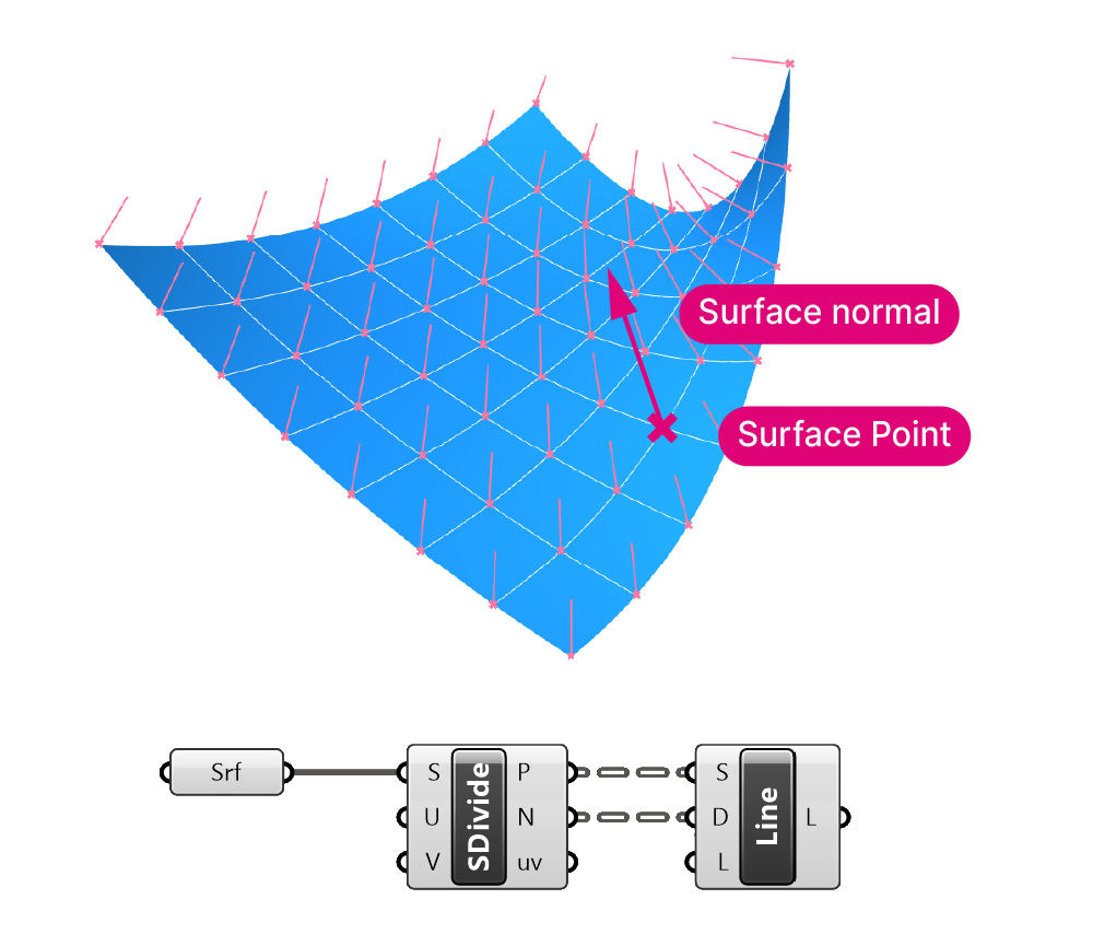
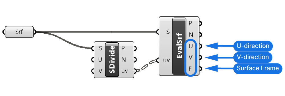
The third output is the UV-value of each point (uv). As we’ve learned, each point on the surface can be described by a pair of numbers. These numbers precisely pinpoint the position of the point along the U and V direction of the surface. The Divide Surface component takes care of generating these values and outputs the points directly. If needed, we can also use these UV-values to extract more information.
By using an Evaluate Surface component, connecting the same input surface and as well as the uv-value output, we can extract additional surface properties at the point. For example the surface frame – a local construction plane at the evaluation point. We can also extract the direction of the U and V curves at the evaluation point, for example to extrude elements on the surface in a consistent direction.
Things to consider when you create a grid on a surface in Grasshopper
The U and V values we specify in the Divide Surface component don’t correspond to the number of points it will generate in each direction, it corresponds to the number of divisions those points will create. It will always be one more point than the division number specified.
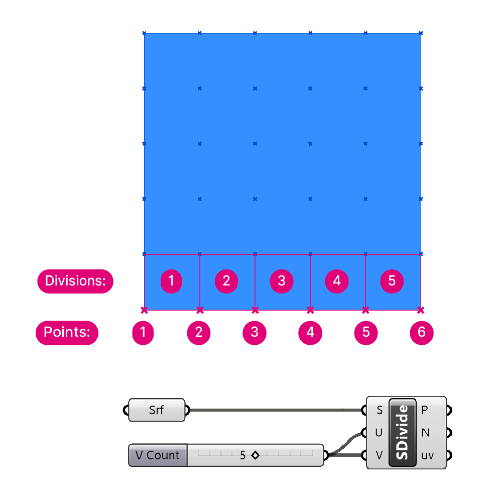
For example, if you add a number slider with a value of 5 in the number of U division input, you’ll get 6 points in the U direction. And if you add a value of 5 to both the U and V division input, you’ll end up with 36 points, not 25!
Keep that in mind to avoid surprises!
Furthermore, if you are looking to divide a surface into a grid of surfaces, you’ll need to use a different approach. You can read more about extracting a subsurface from a base surface in this tutorial: How to subdivide a surface.
Concluding thoughts
In conclusion, creating a grid on a surface in Grasshopper is a simple process once you understand the Divide Surface component and the U and V values of a surface. By using the Divide Surface component, you can easily generate a specified number of points on any surface, whether planar or complex. This technique can be extremely useful for creating complex geometries and patterns in architectural design. I hope this tutorial has been helpful! Happy designing!