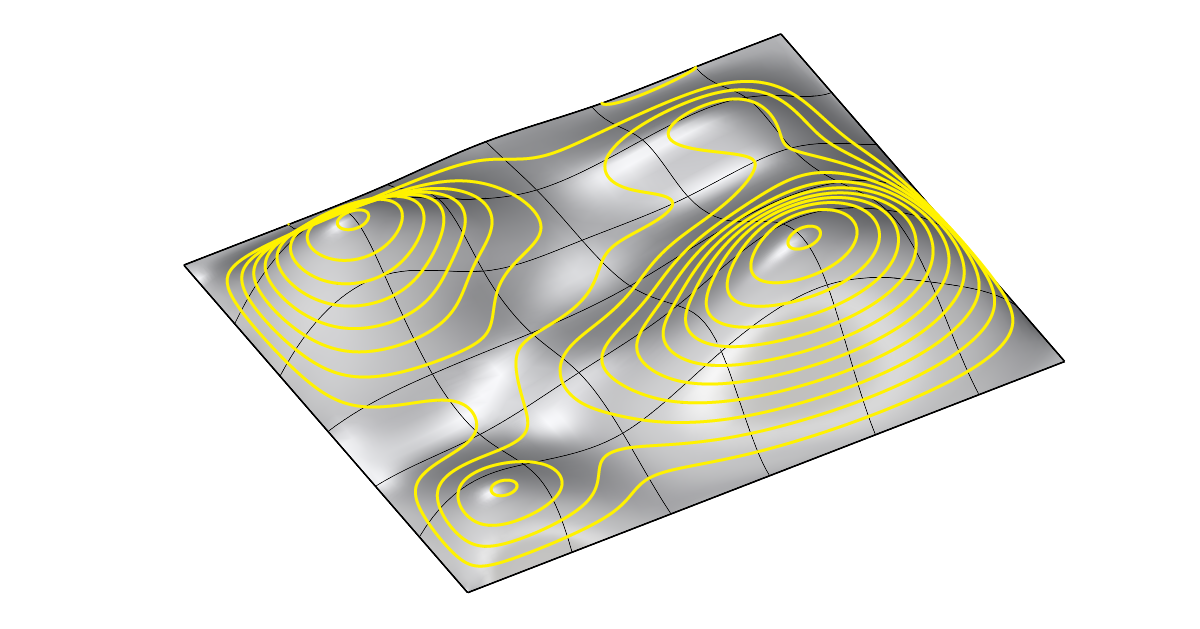
Contour Lines in Rhino allow us to slice surfaces and polysurfaces, creating planar outlines of the object at consistent intervals. In this guide I’ll walk you through each step of the contour command and give you tips and best practices along the way.
How the Contour Command Works
At its core, a contour is a curve formed at the intersection of a geometry and a plane. The contour command essentially creates an array of planes spaced at a distance we specify, and then returns all the intersection curves.
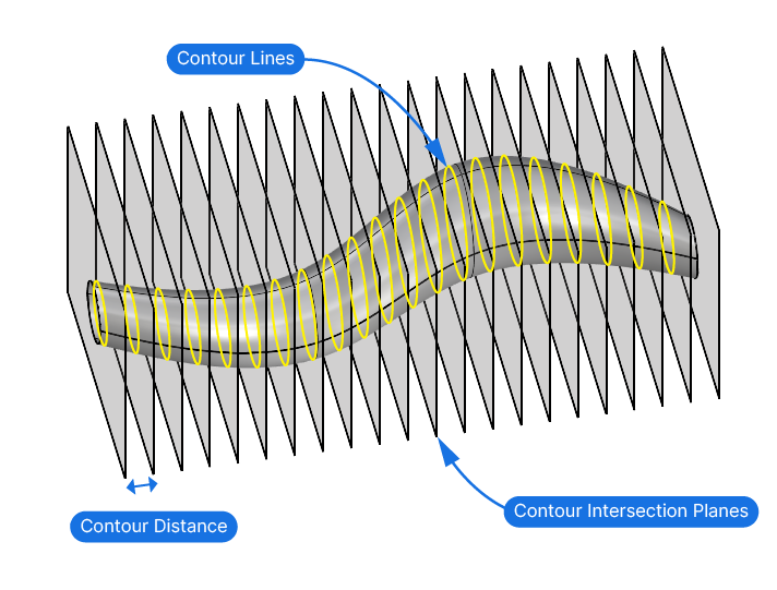
To define the planes, Rhino asks us to specify the vector normal to the plane and the distance between each plane in the array.
The Contour Command Step-by-Step
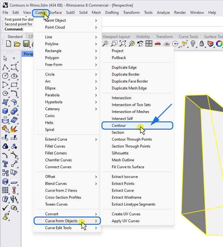
You can find the command in the menu by going to Curve > Curve from Object > Contour.
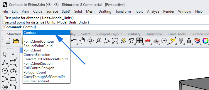
Alternatively, simply type “Contour” into the Rhino terminal and hit Enter.
If you haven’t already selected the geometry before running the command, Rhino will prompt you to select the objects to contour.
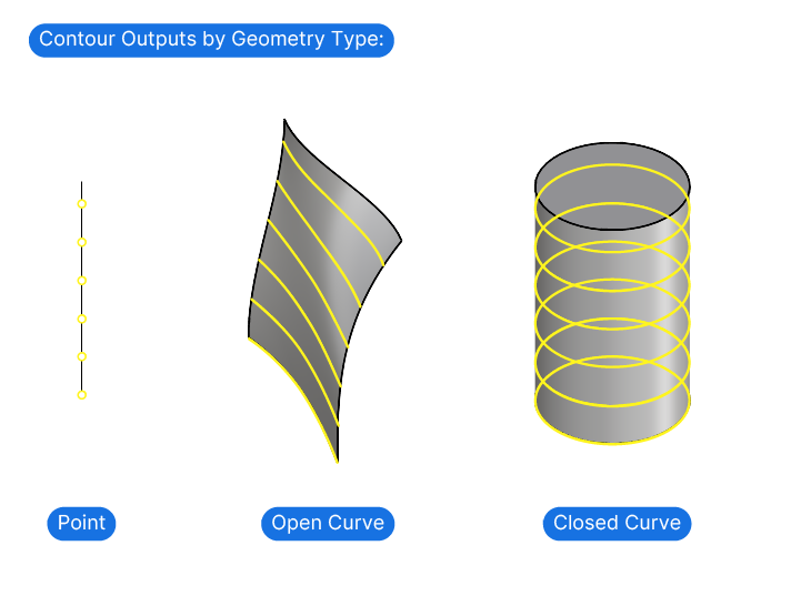
You can select any number and any type of objects: curves, surfaces and polysurfaces. If you contour a curve, you’ll get points at the specified intervals instead of contour lines. To get closed contour lines, make sure the selected objects are closed polysurfaces.
You get to specify a few options in the command line. The only one worth noting is the GroupObjectsByContourPlane option. If you are contouring a complex geometry that results in multiple independent curves for each contour, setting this option to ‘True’ can be helpful later when selecting contours by plane.
Simply click on the option to switch between “Yes” and “No”.

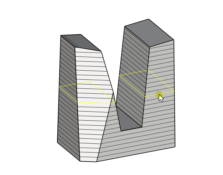
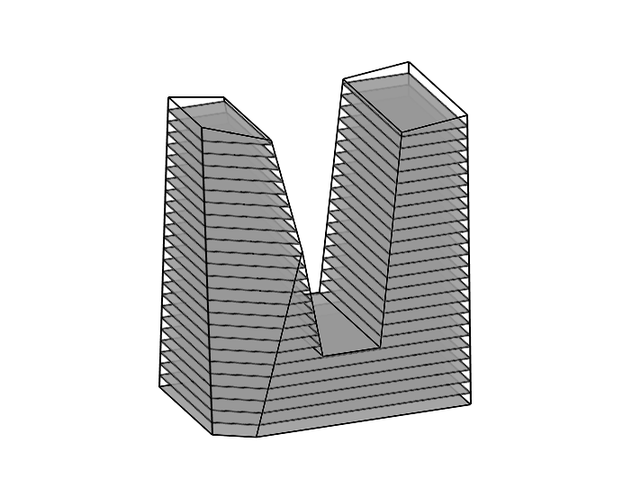
In the example below, the contoured object has two towers, and selecting the contour on one side selects the contour at the same height on the other side as well.
Setting the Contour Direction
The next step is to define the direction of the contour. Rhino wants to know the orientation of the plane to use for the intersection with your selected objects. Instead of asking us to draw a plane, Rhino prompts us to draw a vector that defines the plane’s orientation. The vector we specify will be the normal (perpendicular) to the plane used for the contour command.
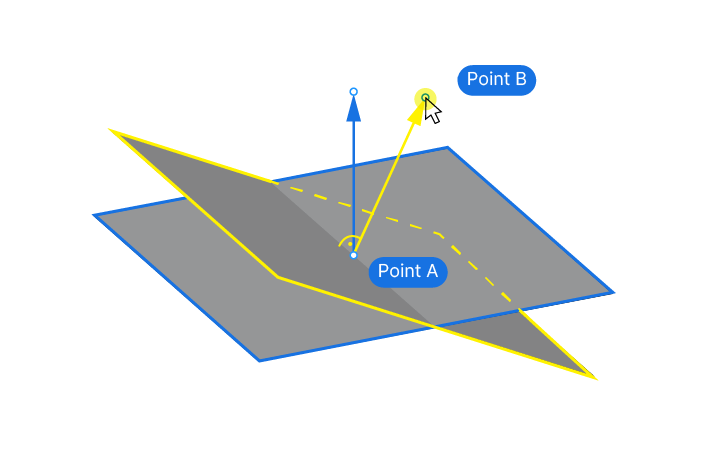
We can define a vector (the direction) in 3D space with two points:
That’s why the Contour command is prompting us to define the first point: the contour base point.
Choosing the Contour Base Point
The basepoint serves two purposes:
- It’s the first of the two points needed to define the direction
- it defines the starting location for the contours.
By defining the base point, we also determine the shift of the intersection planes along the contour direction. In the example shown below, I chose the basepoint at the lowest point of the tower. This is where the first contour will be drawn.
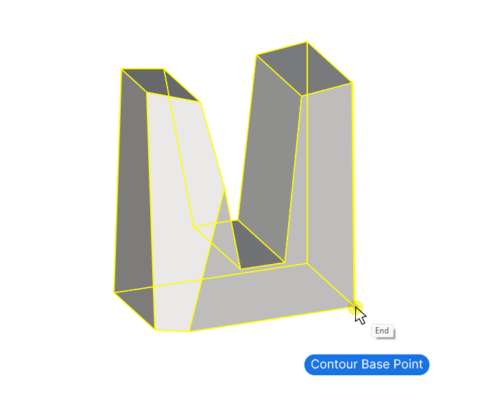
After selecting the base point, Rhino will prompt us to pick the direction perpendicular to the contour planes. In other words we are asked to draw the second point needed to define a directional vector.
Choosing the Direction
In most cases, it’s recommended to use one of the world axes as the contour direction. You can snap the cursor to the world axes by holding down SHIFT, and moving the pointer towards one of the directions. Keep in mind that you can use any of the 4 viewports to pick the direction!
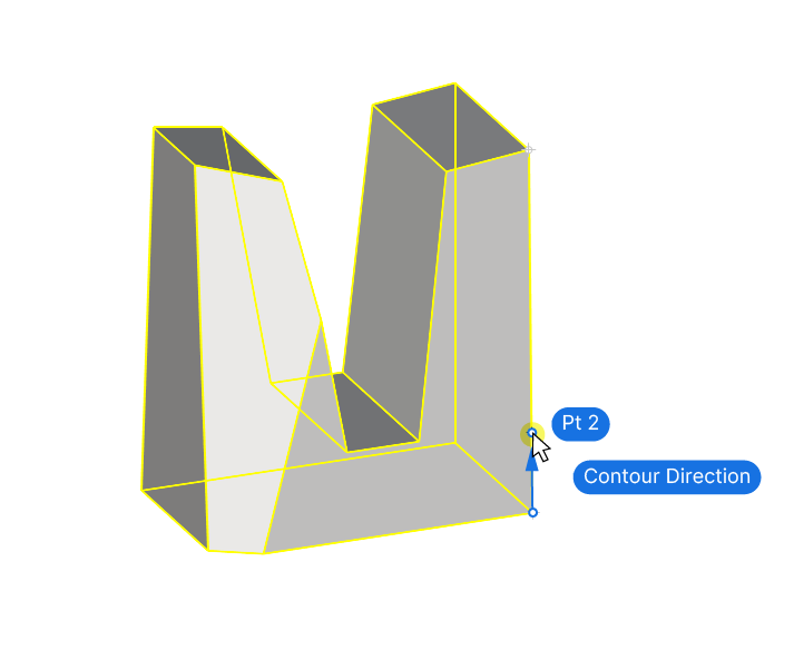
It doesn’t matter how distant the point is from your basepoint. At this stage Rhino only wants to know the direction of the contour planes. The distance is specified in the next step.
If you’re modeling in a maximized perspective viewport, you can pick the direction without switching to the default 4 views. You can do so by specifying the relative coordinates of the next point in relation to the base point.
To specify a relative point, for example 1 unit along the z-axis, type:
r0,0,1 (r stands for relative, followed by x,y,z coordinates)Simply start typing, the text will be added at the end of the command. Then hit Enter to confirm.
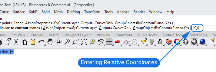
If we just typed “0,0,1” Rhino would interpret the coordinates as absolute world coordinates, and draw the point next to the world origin. The “r” right in front of the coordinates turns them into coordinates relative to the last active point.
Setting the Contour Distance
Next the prompt will ask for the contour distance. Simply type the distance you want between each of the contours.
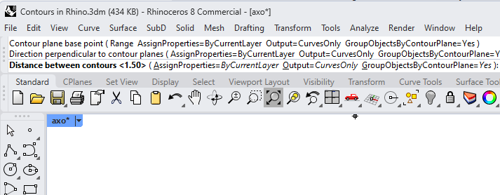
If you type only a number, Rhino will use the document units. To specify custom units, add the unit after the number (e.g., 3m, 320cm, or 120in).
Once you confirm with Enter, Rhino will create the contour lines. The command will complete with all the newly created contour lines selected.
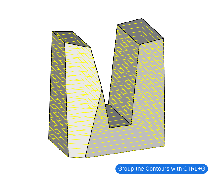
I recommend pressing CTRL + G to group them, so you won’t have to reselect them manually.
Turning the curves into Surfaces
The natural next step after creating the contour lines in Rhino is often to turn them into surfaces. To do so, go to Surface>Planar Curves.
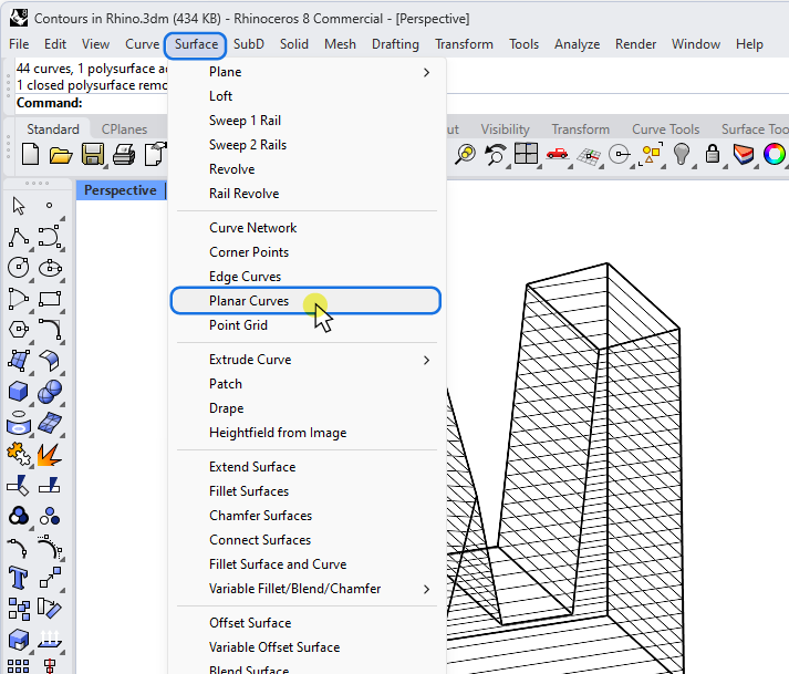
Or select the “Surface from planar curves” command from the toolbar here:
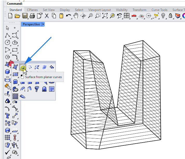
The Planar Curves command will create a surface for each closed curve while considering all curves on the same plane. It will interpret curves within curves as ‘holes’ and create a perforated surface.
Limiting the Contours to a Specific Range
If you want to apply the contour command to only a specific section of a longer object, you’ll notice that contours don’t have a defined start or end point: The contour command creates an infinite array of planes along the direction we specify and generates a contour line for every intersection it finds. The contour base point is merely defining the ‘Shift’ along the chosen contour direction.
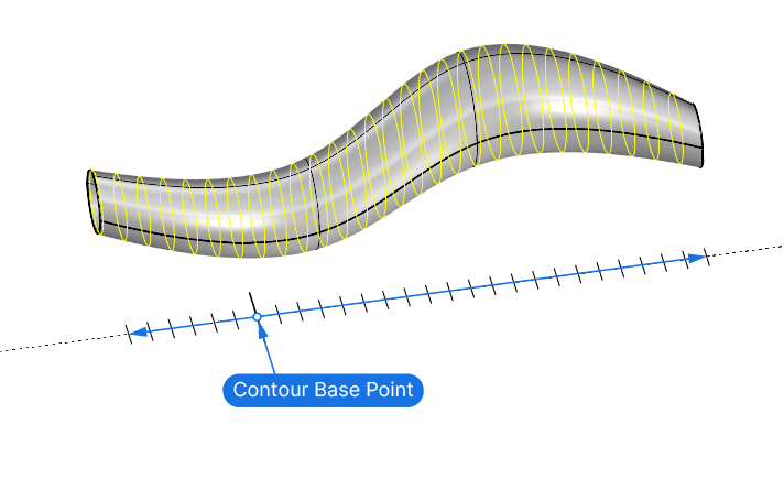
Even if we pick the base point in the middle of the object, the contours will still run through the entire object. To solve this we can specify the range within which we want the contours to be created.
You can access this range setting in the command line options. Click the ‘Range‘ Option in the command line.
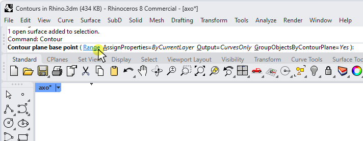
Similar to when you pick the contour direction, you’ll be asked to specify two points. Use the two points to mark the beginning and end point of where you want to contours to be drawn.
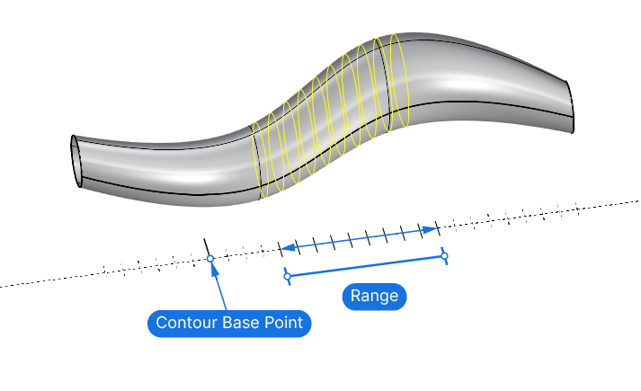
Any contours will only be created if they fall within the range specified.
Creating Parametric Contours in Grasshopper
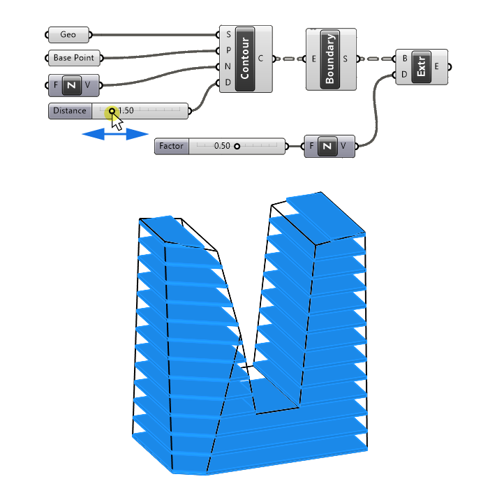
If you are going through a lot of design iterations, it can be tedious to run the Contour command every time.
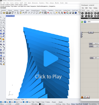
To save time and make your design workflow more efficient, you can create a simple Grasshopper script that will create the contour lines on the fly, so you can focus on perfecting the shape of your design. You can create surfaces and extrude on the fly as well, for an interactive modelling experience.
Conclusion
Contour lines are a great way to rationalize the complex shapes we can create in Rhino. Whether it’s floors of a massing study or laser-cutter files, they can bring our designs to life!
Happy modeling!

