Rhino is an unrivaled powerhouse in the realm of 3D modeling, breathing life into our design ideas. Its versatile modeling modes – surfaces, meshes, and SubDs – allow us to model virtually anything, but this flexibility comes at a cost. Transforming one geometry type into another can be a frustrating undertaking. One such hurdle often faced by designers is the transformation of a mesh into a surface in Grasshopper.
In this guide, we’re going to break down two different ways to tackle this problem. Both ways have their own pros and cons, and knowing them will help you choose the one that works best for your situation.
Let’s get right to it!
Understanding Mesh-to-Surface Conversion in Grasshopper
Before we get our hands dirty at the Grasshopper component level, let’s understand how meshes and surfaces differ to understand how we can convert one to the other.
What is a Mesh in 3D Modelling in Grasshopper?
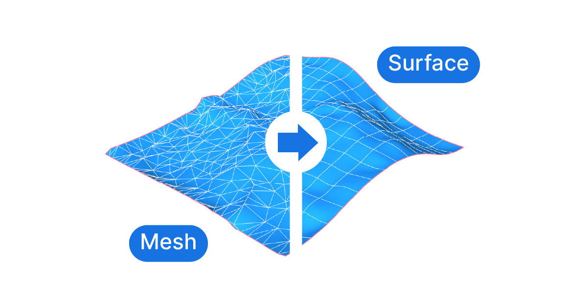
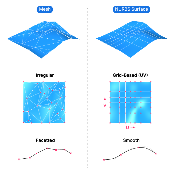
Meshes is a 3D modelling approach where objects are described by “faces”, small triangles, “quads” or so-called “n-gons”. These faces are organized edge to edge to describe the boundary of an object. Meshes are made of three components: vertices (the corner points), faces (the surfaces) and edges.
Meshes are extremely lightweight, computationally speaking. They can have several hundred thousand faces and still display and render very quickly. This makes them great for representing complex terrain models in all their detail.
While meshes can appear smooth, in truth they aren’t. Meshes approximate a smooth surface by breaking it down into small mesh faces. The more faces, the smoother the appearance.
Now how does that differ from a NURBS Surface?
NURBS Surfaces in Grasshopper: An Brief Overview
NURBS, short for Non-Uniform Rational B-Splines, is a mathematical representation of 3D geometry. In simpler terms, it’s a way to create smooth, complex shapes in 3D modeling. A NURBS surface is made up of ‘control points’ that define its shape. Think of it like a flexible sheet, and these points are where you pin the sheet down.
There are also curves that run through these points, called ‘U’ and ‘V’ directions, like two threads in a fabric. These directions help to shape and control the surface. Together, the control points and the U/V directions give you a lot of control over your 3D shape.
Unlike meshes, which can have an irregular tessellation or edge pattern, surfaces are always based on a grid are essentially a rectangular “sheet”, that can be warped and twisted in space.
The Challenges of Converting Mesh to Surface in Grasshopper
This differences in the way meshes and surfaces are constructed creates some challenges when it comes to converting one to the other. The main issue is that they use different 3D reference points to generate their geometry, vertices for meshs, and control points for surface.
Since the two 3D modelling techniques are so different, there is no way to create a precise 1-to-1 conversion from one type to the other. It’s important to understand that any conversion will lead to a compromise in accuracy, speed or usability of the resulting output.
Practical Techniques for Mesh to Surface Conversion in Grasshopper
We’ll look at two different techniques to convert a mesh to a surface in Grasshopper, both suited best for a specific use case.
The kind of mesh you are trying to convert, and what you want to do with the resulting surface will determine which method to use.
We’ll look at the following two examples:
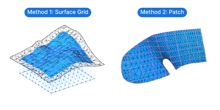
Method 1: Turning a mesh into surface by creating a brand new surfaces based on a point grid.
Method 2: Creating a patch surface that runs through the mesh vertices and trimming the surface.
Method 1: Grasshopper’s Mesh to Surface Grid Method
Imagine you have an extremely detailed mesh terrain model with several hundreds of thousands of faces. You just need a small portion of the terrain, and you want to convert it to a surface, so modelling it will be easier and the cleaner.
Turning the mesh into a polysurface (or, as it is called in Grasshopper, a Brep) is not an option: the sheer number of mesh faces would lead to a huge, slow file.
Instead, we’ll use a method that approximates the mesh shape while allowing us to define the accuracy of the surface.
Here is how to convert a mesh to a surface with the ‘Surface Grid’ method:
- Draw a rectangle in the top view that defines the area to convert into a surface.
- Subdivide the rectangle to generate a grid of points.
- Find the vertical intersection between those points with the mesh.
- Turn those intersection points into a single, clean surface.
Let’s see how to turn this logic into components with an example.
Implementing the Mesh – Surface Grid Method in Grasshopper: A Step-by-Step Tutorial
Step 1: Initial Setup
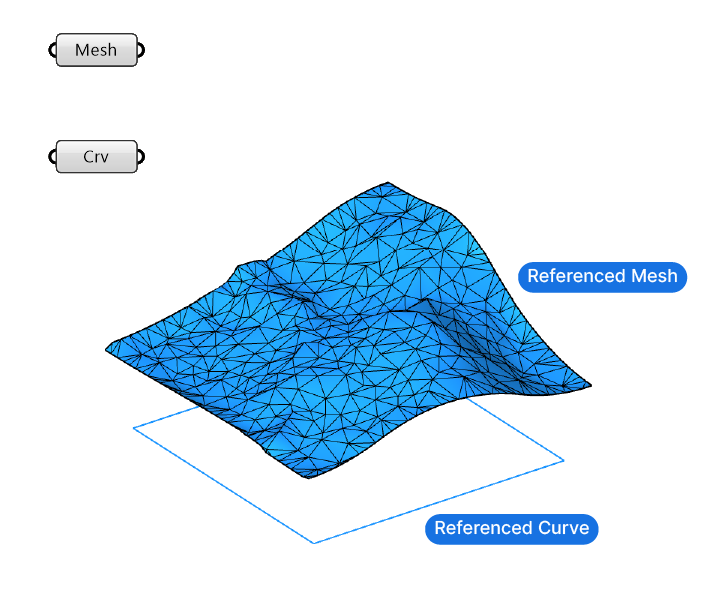
Let’s start by referencing a mesh from Rhino to a Mesh data container in Grasshopper.
Let’s also draw a rectangle in the top view to mark the area of the mesh we want to turn into a surface. Then add a curve container and reference the curve to it. It’s important that the curve is fully inside the mesh we want to convert. The rectangle can cover the entire mesh or just the area we interested in converting to a surface.
Step 2: Rectangle Subdivision
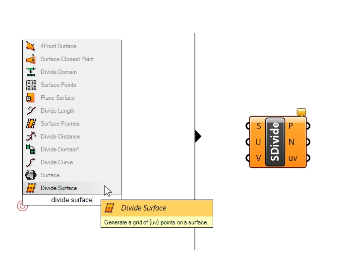
Now let’s subdivide the rectangle. We can simply add the ‘Divide Surface‘ component, and connect the Curve to it. Grasshopper’s automatic data conversion takes care of turning the planar curve into a surface for us.
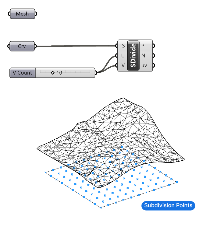
Let’s add a number slider and connect it to both the U and V input. In my example I have a square, so I’ll use the same value for both. Adjust the U and V numbers in case you have a elongated rectangle. The aim is to get a uniform distribution of points.
The resulting point grid is the ‘resolution’ of the surface we’ll be creating.
Step 3: Intersection Points and Mesh Re-sampling
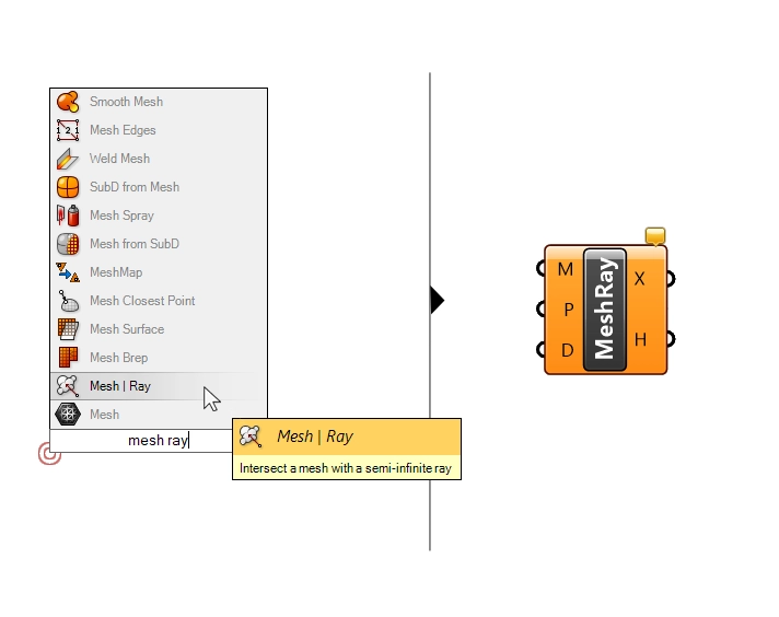
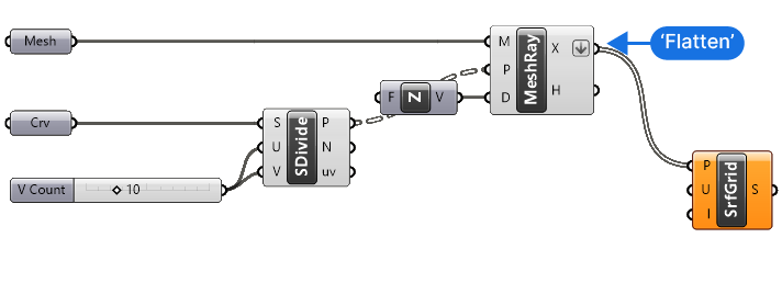
Next, let’s find the intersection points between the mesh and vertical lines starting at the point grid we generated. We’ll use a component called ‘Mesh | Ray‘ Intersection. You can add it to your script by double-clicking onto an empty spot on your canvas and typing ‘Mesh Ray‘. Click on the component to add it.
Instead of having to model vertical lines, this component allows us to find the intersections by providing a point and a direction input. In 3D modelling, a “ray” is an infinite line define by a location and direction.
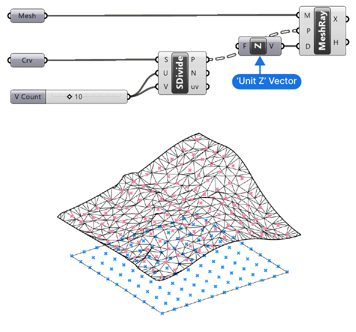
Let’s connect our mesh to the Mesh (M) input, the points to the Ray Start Point (P) input and a ‘Unit Z’ vector to the Ray Direction (D) input. To add the ‘Unit Z’ vector, write ‘z’ into the component search bar. The Unit Z component simply contains a unit vector with the coordinates { 0, 0, 1 }. In other words a vector pointing upwards.
The ‘X’ output of the Mesh | Ray Intersection component contains our intersection points with the surface.
Because a mesh is based on triangulation and often irregular edge patterns, generating a grid and finding the intersection points allows us to ‘re-sample’ the mesh into a regular grid, which NURBS surfaces are based on.
Step 4: From Grid to Surface
Now comes the last and crucial step: turning this grid of points into a surface.
We’ll need a component called ‘Surface from Points (SrfGrid)‘. Type ‘SrfGrid‘ or ‘Surface from Points‘ into the component search bar to add it to your script.
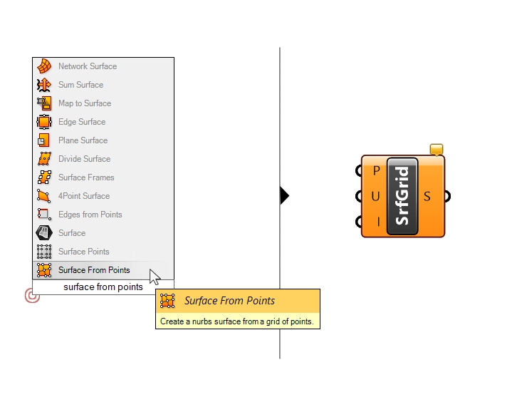
In essence, this component will take a list of points and turn them into a surface. But it’s not quite as simple as that: the points must be in a very particular order. The points need to be sorted row by row, all in sequence.
The good news is that we don’t need to worry about any of that, because we generated the points by dividing a surface – so the point order is already correct!
What we need to do though, is flatten the point list. The ‘Surface from Points’ component requires a single list containing all the points.
Since all the points are in a list, the component needs a way to understand how they are organized into the U and V directions. That’s where the second input, the ‘UCount’ comes in. The UCount defines the number of points in the ‘U’ direction (U and V describe the two directions of a surface grid).
Step 5: Defining the UCount and Finalizing the Surface
We’ve already encountered U and V values in our script: we defined the number of subdivisions of our rectangles in both the U and V direction.
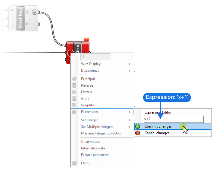
Let’s connect the U number slider value to the ‘U’ input of the ‘Surface from Points’ component. We’ll get an error saying that the UCount isn’t valid for the number of points we provided. The reason for that is that the number of subdivisions we defined is the number of segments between the points, and now we need the actual amount of points.
To get it, we simply need to add 1 to the ‘U’ input. The easiest way to do that is to right-click on the ‘U’ input, go to ‘Expression’, type in ‘x + 1’ and commit the changes.
The surface will now appear in the viewport.
By changing the number slider value we can change the number of subdivisions, thereby allowing us to adjust the ‘resolution’ of the resulting surface.
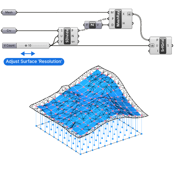
Keep in mind that surfaces with too many controlpoints will be heavy, so be careful when using the number slider, especially when going beyond a values of 100. Grasshopper might freeze.
Understanding the Benefits and Drawbacks
The strong point of this method is the fact that we get a single, clean surface. In addition, we can easily adjust the ‘resolution’ of our surface, giving us control over the accuracy of the mesh to surface conversion.
The disadvantage of this approach is that the resulting mesh is clearly an approximation of the original mesh. Depending on the source mesh and the surface subdivision, the deviation may be quite visible.
For this method to work, it’s essential that the mesh that is being intersected doesn’t have any holes. If one of the intersection fails because a ‘ray’ doesn’t intersect the mesh, the point grid will have an uneven number of points and the ‘Surface from points’ component will fail to create the surface.
It is ideal for cases where the source mesh is very complex, perhaps made of several meshes joined together.
Method 2: Grasshopper’s Mesh to Surface Patch Method
In some cases, you’ll want to convert a mesh to a surface in Grasshopper in order to get a clean and precise, trimmed surface. The previous method doesn’t work in that case: the Surface Grid approach requires a rectangular, planar outline.
What if the mesh we are trying to convert is a 3D shape with a clearly defined, non regular boundary?
In that case the Surface Patch method may be the best option.
This Surface Patch method works as follows:
We extract all the vertices from the mesh and use them as the input for a Surface patch. The surface patch will fit a surface through all the points provided, even if they are in a random order. Because the surface patch will create a surface that goes beyond the points we specify, we’ll need to trim it.
That’s why we’ll extract the exterior edges of the mesh, project them to our surface patch, and the split the surface with them.
The last step will be to select the correct surface among the split surfaces.
Let’s go through it step-by-step.
Converting Mesh to Surface Using Grasshopper’s Patch Method: A Step-by-Step Tutorial
Step 1: Initial Setup and Mesh Deconstruction
Once again I’ll start with a mesh container and reference the mesh I want to convert to a surface from Rhino.
The first step will be to get the vertices of the mesh. To do that, we’ll use the ‘Deconstruct Mesh‘ component.
Double-click on an empty spot on the Grasshopper canvas and type ‘Deconstruct Mesh’ into the search bar. Click on the component to drop it to the canvas.
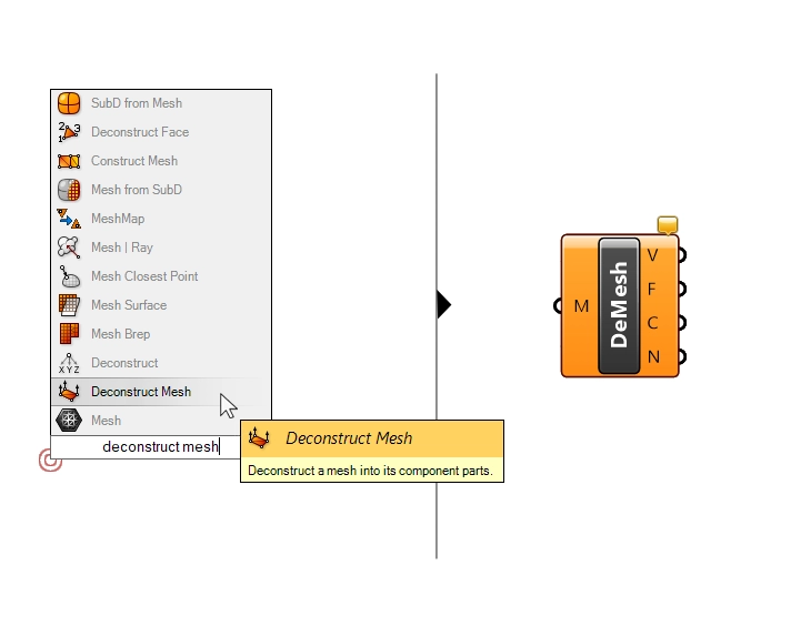
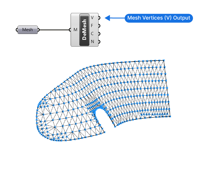
This component will output the vertices (points), faces, edges and normals of the mesh.
Step 2: Using the Patch Component
Next, we’ll need the ‘Patch‘ component. Once again type ‘Patch’ into the component search bar to add it.
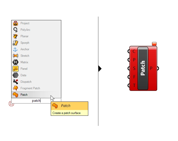
The Patch component will fit a surface through a set of curves or points, the ‘C’ and ‘P’ inputs respectively. We can provide just one or the other, or even both. In our case, we’ll just plug in our mesh points.
Let’s take the Vertices (V) output of the ‘Deconstruct Mesh’ component and connect it to the ‘P’ input of the Patch component.
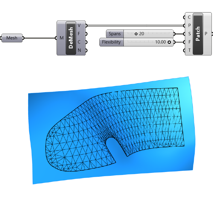
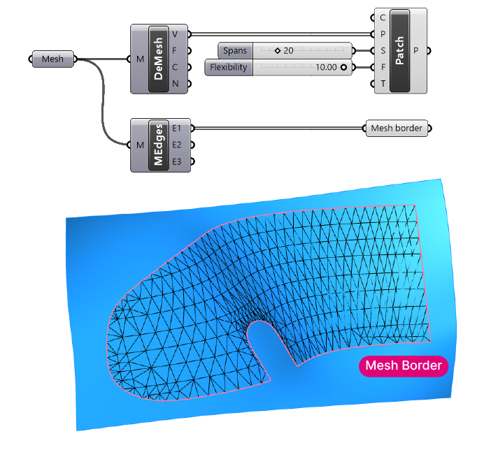
In the viewport we’ll see the result: the resulting surface attempts to fit through as many points as possible. The result is a rectangular, deformed surface that extends beyond our original mesh.
We can tweak the look of the patch surface with the Spans (S) and Flexibility (F) inputs of the Patch component.
The ‘Spans’ input will define the number of controlpoint rows and therefor affect the ‘resolution’ of the resulting surface. A higher number will result in a more accurate match to the mesh, but also a heavier file. Let’s add a Number Slider with a value of 20.
The ‘Flexibility’ input defines how “flexible” the surface is. A high flexibility value will make sure that the surface closely matches the input mesh. If the mesh has irregularities, less flexibiliy can lead to a smoother surface. Let’s set the Flexibility to ’10’ with a Number Slider.
Let’s generate the trim curves next.
Step 3: Generating Trim Curves
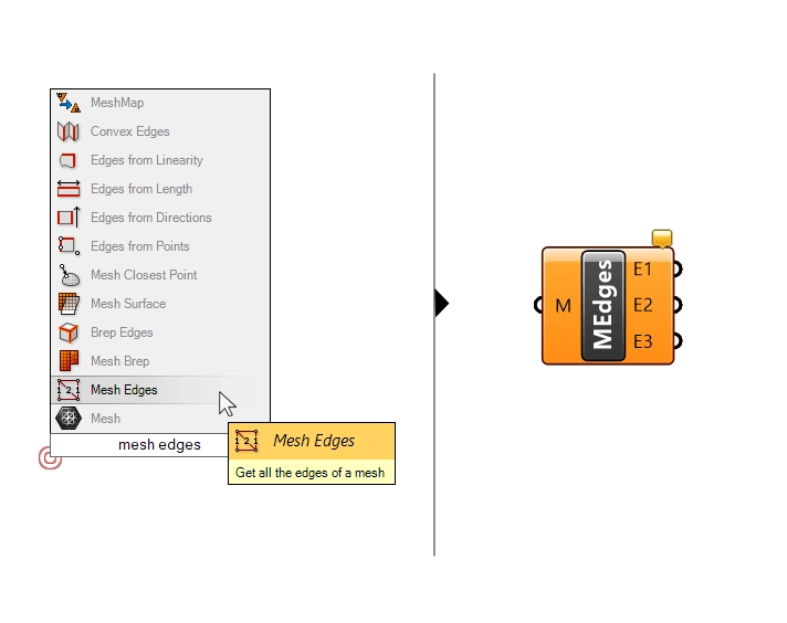
Let’s add a ‘Mesh Edges‘ component. The component will output the mesh edges in three categories: ‘naked’ edges, which are edges that are not shared with another other faces, in other words the border edges, ‘interior edges’ and ‘non-manifold edges’. We are going to use the ‘naked edge’ in the output ‘E1‘.
Let’s add a Curve Data Container and name it “Mesh Border”.
Step 4: Splitting and Selecting the Surface
Next, we are going to use the ‘Pull Curve‘ command to “pull” the curve onto the surface.
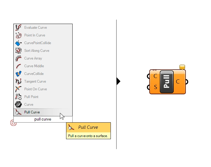
The component asks for the curve to pull, which is out E1 edges, and the surface to pull them to, which is our patch surface.
Great! Now we can split the patch surface with these border curves. We’ll add a ‘Surface Split‘ component, and connect the surface, as well as the splitting curves.
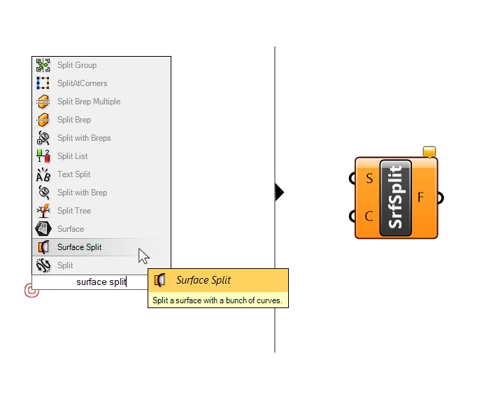
The resulting output is the split surfaces.
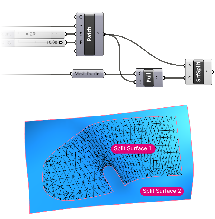
Now we need to pick the surface we want to keep.
A manual way to do it would be to use the ‘ListItem’ component and pick the surface we want with a number slider. But the order of the split surfaces in the list is largely arbitrary, which means if the mesh input changes, chances are, so will the ListItem number.
Instead, let’s build a more robust algorithm that will only select the surface that matches the source mesh.
Bonus Step: Building a Robust Algorithm for Surface Selection
We’ll only need the surface input containing the split surfaces, and the original mesh. Here is the selection process:
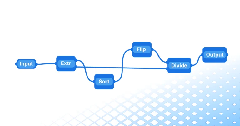
We use the ‘Populate 3D‘ component to generate a number of points on each of the split surfaces.
Then we measure the distance from the resulting points to the original mesh with the ‘Mesh Closest Point‘ component.
We’ll use the ‘Distance‘ component to measure the distance from the populated points to the closest points on the mesh.
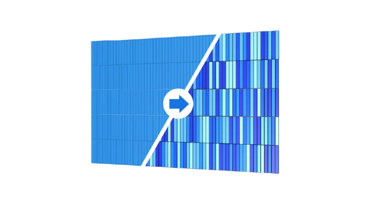
The next step is to sum up all the distances to the mesh for each split surfaces. The ‘Mass Addition‘ component will create the sum for us. The surface with the shortest sum of the distances to the mesh is in all likelihood the surface we want.
So let’s use the ‘Sort‘ component and sort the flattened sums and the split surfaces in parallel.
Finally, let’s pick the first item in the sorted split surfaces list with a ‘ListItem‘ component. We can add a surface container to create a clean finish.
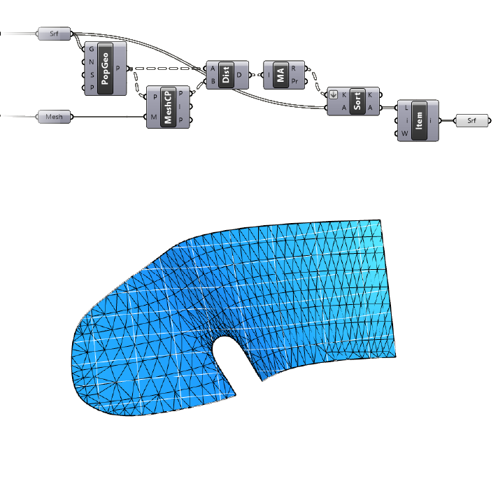
The result is very close approximation of the original mesh, with the same outline as the mesh.
The Bottom Line
To wrap things up, transforming a mesh into a surface within Grasshopper may seem daunting, but it becomes manageable when broken down into systematic methods. Both techniques we’ve explored – Re-sampling the surface from scratch and using the Patch component – offer their own advantages and drawbacks. Understanding these nuances allows you to pick the one that best suits your project needs.
I hope, with the help of this guide, converting a mesh to a surface in Grasshopper will feel like second nature. Keep designing, keep learning, and most importantly, keep pushing the boundaries parametric design with Rhino and Grasshopper!
Happy designing!