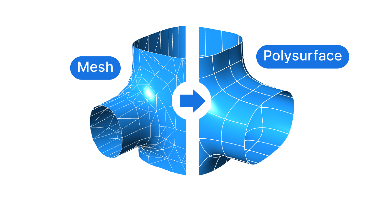
In Grasshopper, converting a mesh to a polysurface can seem daunting at first. But with the right approach, it’s an operation that can unlock a new realm of possibilities for your designs.
In this guide, we’ll be diving deep into two distinct methods for transforming a mesh to a polysurface in Grasshopper. Both these methods are tried and tested, providing you with the flexibility to choose the one that best suits your specific needs.
If you are trying to convert a mesh to a single NURBS surface, instead of a polysurface, check out the following tutorial: Mesh to Surface in Grasshopper.
Let’s get right to it!
Method 1: Mesh to Facetted Polysurface
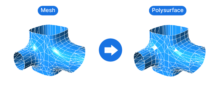
Since a Mesh is made of several smaller “faces”, the simplest approach is to convert each of them into a NURBS Surfaces, and then join them to create a polysurface. It’s the quickest and easiest way to turn the mesh into NURBS geometry.
This technique leads to a polysurface that looks identical to the Mesh. All points and edges will be the same.
To convert a mesh to a polysurface, we’ll follow these steps:
- Convert the outlines of each mesh face into a polyline.
- Generate a surface for each polyline
- Join the surfaces to create a polysurface.
Step-by-Step Guide to the Mesh to Polysurface Technique in Grasshopper
Step 1: Initial Setup and Face Extraction
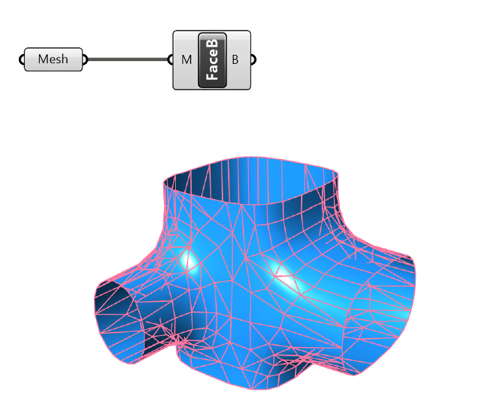
Let’s start by adding a Mesh data container and either referencing the mesh from Rhino, or connecting the mesh from elsewhere in your script.
Next we’ll extract the outline of each of the mesh faces. To do that, let’s add the ‘Face Boundaries’ component. Double-click on an empty spot on the Grasshopper canvas and type ‘Face Boundaries’. Then select it to add it to your script.
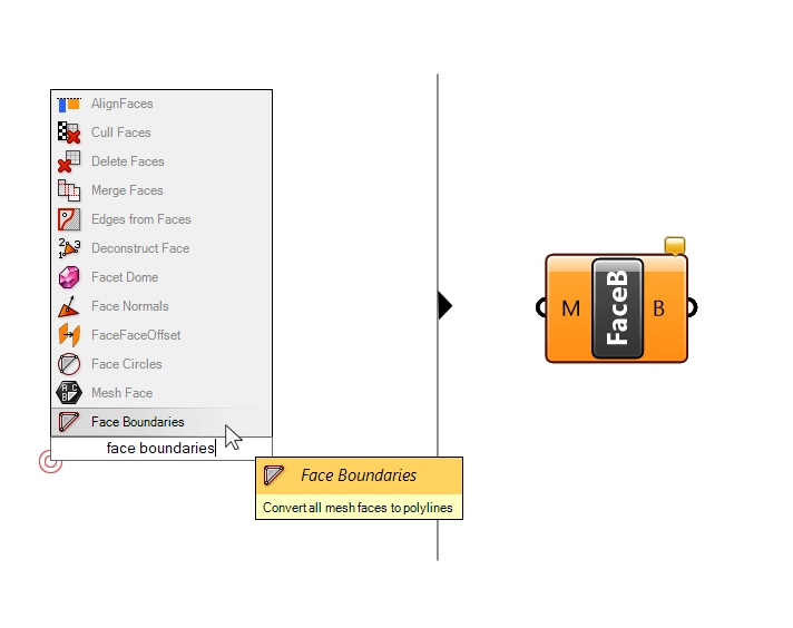
The output ‘B’ of the Face Boundaries component contains a list of closed polyline curves, one for each mesh face.
Unlike the ‘Deconstruct Mesh’ component, which outputs edges as single lines, the ‘Face Boundaries’ component joins all the edges of a face that belong together, and creates a closed polyline.
Step 2: Converting Curves into Surfaces
Next, we’ll convert these closed curves into surfaces by taking advantage of Grasshopper’s automatic data type conversion.
Let’s add a Surface container and simply connect the curves to it. Grasshopper will automatically turn the curves into surfaces, even if the polylines are not completely planar. Since, with few exceptions, meshes are made of triangles or “quads” (faces with four edges), the conversion will go smoothly.
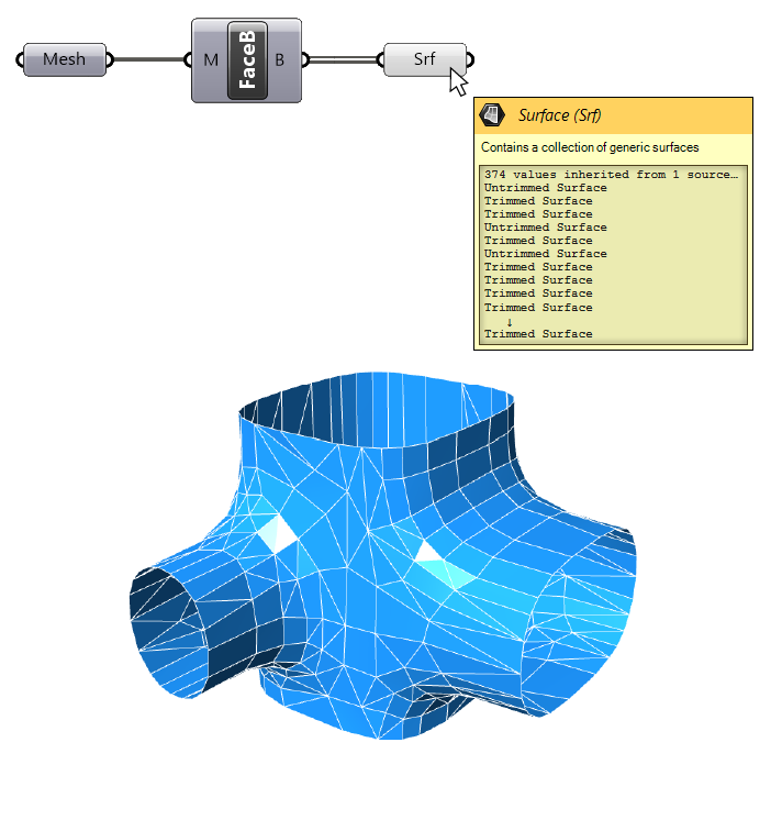
While the preview looks good in the Rhino viewport, we are in fact still dealing with individual surfaces. By hovering over the surface data container, we see that we get a list of individual surfaces.
Let’s join them.
Step 3: Creating a Polysurface or Brep
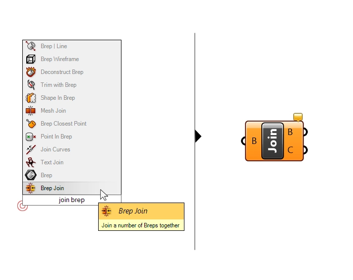
The final step is to join all the surfaces to create a polysurface, or Brep.
Let’s add a ‘Brep Join‘ component, and connect our surfaces.
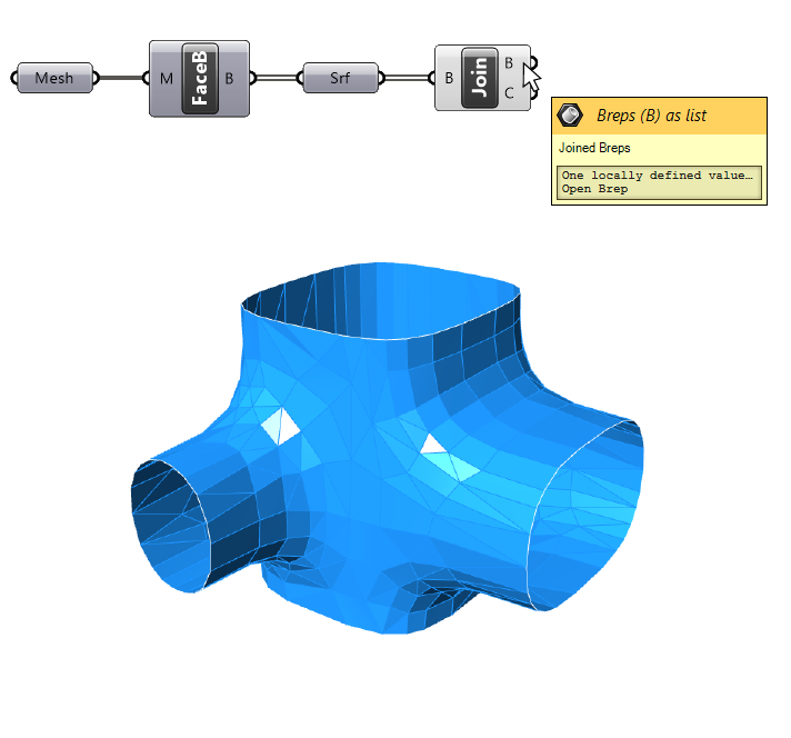
That’s it! We now have a polysurface (called “Brep” in Grasshopper) that accurately represents the mesh.
Benefits and Disadvantages of Polysurface Conversion
Turning the mesh into a polysurface leads to a geometry that stays true to its source. Every point and every edge is precisely converted.
The main drawback of this method is that NURBS Surfaces’ precision comes at a computational cost. Turning hundreds, often thousands of Mesh faces into Surfaces, and then joining them to a Polysurface can lead to a very heavy, slow file.
In addition, handling the facetted Polysurface is probably no easier than modifying the Mesh itself.
If the main intent was to ‘clean up’ the Mesh, nothing has changed, as the resulting Polysurface looks as complex as the Mesh source.
Recommendations for Using This Method
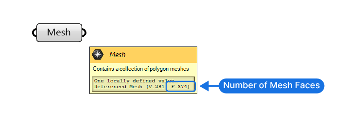
Since complex meshes with thousands of faces can take a long time to convert and may even crash Rhino, always check the number of faces the mesh has before using this approach.
You can see the number of mesh faces by hovering over the Mesh data container in Grasshopper.
If the mesh was modelled in Rhino, select the mesh and type “What” into the command line. A window will appear, listing the number of vertices and faces.
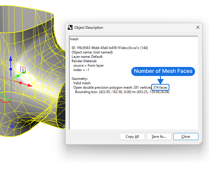
If the mesh exceeds 2000 faces, its better to consider the following method.
Method 2: Mesh to Simplified Polysurface Method
Chances are, that if you are trying to convert a mesh in Grasshopper, you are trying to create a cleaner geometry. Turning a mesh into a facetted polysurface, as shown in Method 1, doesn’t simplify the geometry, in fact it only makes it ‘heavier’.
Given the complex topology of our example mesh, there is no way around creating a polysurface, but what we can do is convert the mesh into a simplified polysurface.
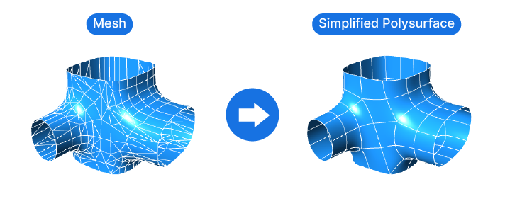
To simplify the output, we’ll first remesh the source mesh into “quads”, and then turn that simplified mesh into a SubD. From there, we can easily convert it to a polysurface, or Brep.
Implementing the Mesh to Simplified Polysurface Method: A Step-by-Step Tutorial
Step 1: Initial Setup and Quad Remesh
Once again, let’s start with a Mesh data container and reference a mesh from Rhino, or connecting a mesh created elsewhere in the script, for example a mesh created from points.
The first component we’ll use is the ‘Quad Remesh‘ component. Add it to the canvas by typing the name into the component search bar.
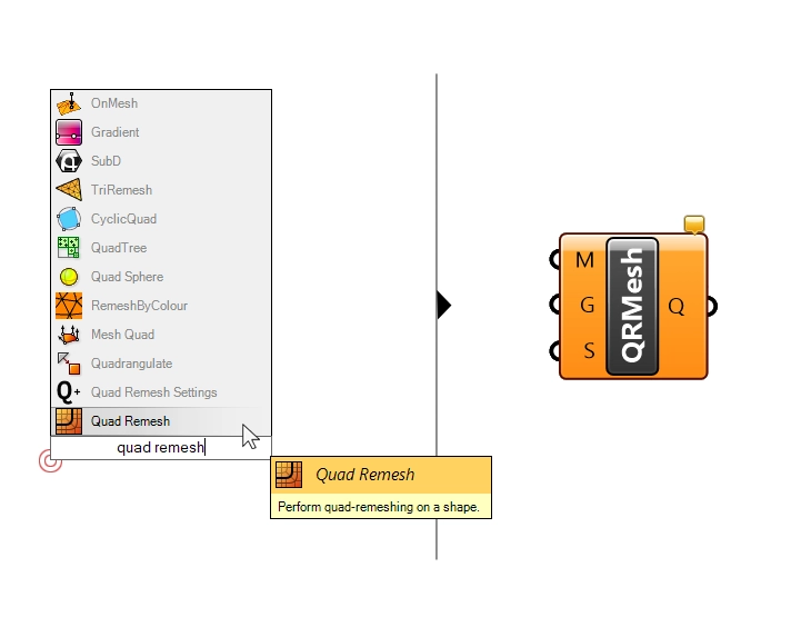
This component “remeshes” the source mesh using “quads”, or rectangular faces. Rectangular faces are closer to NURBS Surfaces’ underlying logic, leading to a cleaner result in the end.
By default, the ‘Quad Remesh’ component will create a mesh with approximately 2000 faces.
The component has three inputs: the first input asks for the mesh to operate on – let’s connect our mesh to it.
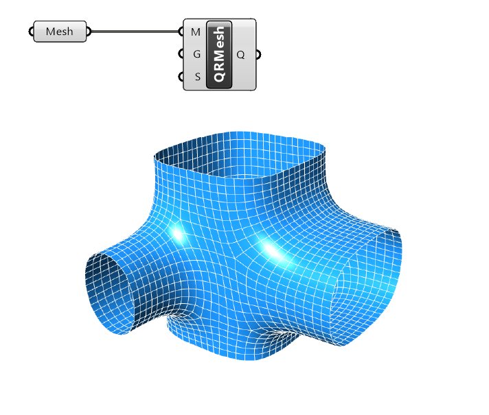
Pretty neat, right?
Step 2: Customizing the Remesh Settings
The second input ‘G’ is optional, it gives us the opportunity to define “guide curves” that will be taken into account as a starting point for the resulting quad mesh.
The last input ‘S’, contains the settings the mesh will be remeshed with. Let’s make some adjustments to get an even simpler mesh.
We can specify custom settings with an additional component called ‘Quad Remesh Settings’.
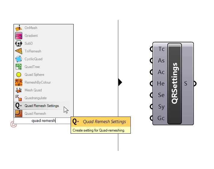
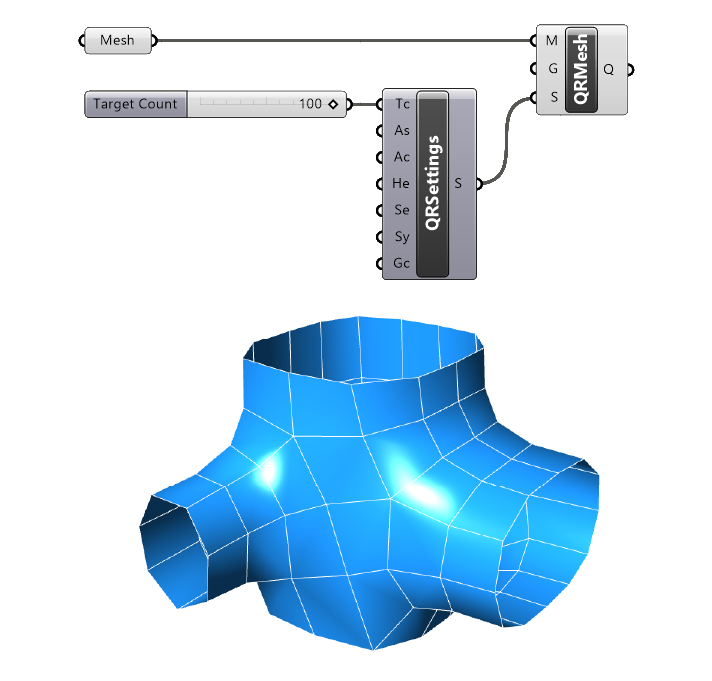
The component allows us to tweak several meshing settings, but the most important one is right at the top: the target count. This value is number of “quads” the component will target in the remeshing process.
To simplify our final output, let’s add a number slider and specify a value of 100.
The resulting mesh will look very jaggy, but don’t worry, it will turn smooth again in the next step.
Step 3: Converting the Mesh to SubD
Now let’s turn this lower-poly mesh into a SubD!
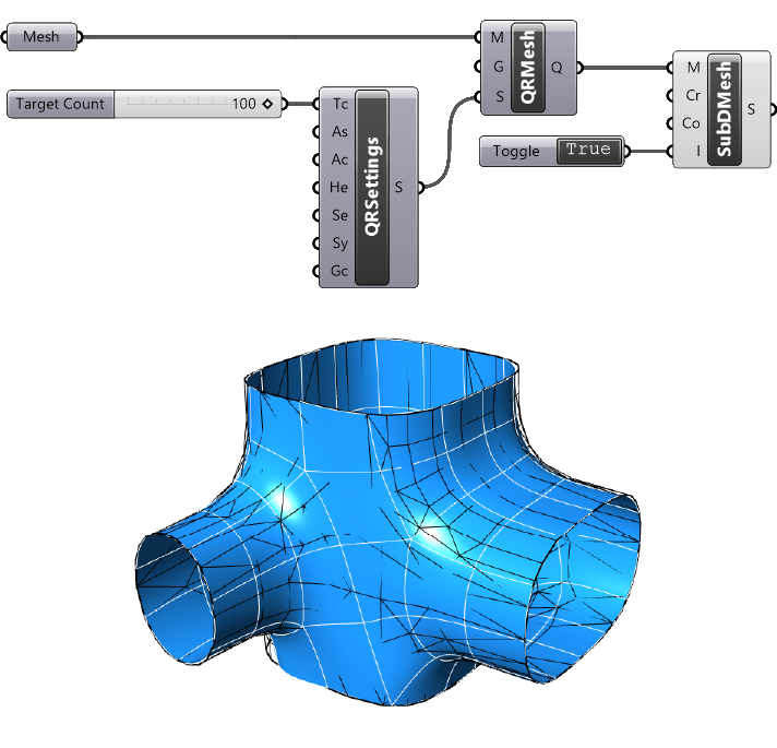
Type ‘SubD from Mesh’ into the component search bar and select it to add it to the Grasshopper canvas. As the name suggests it will generate a SubD geometry from the mesh.
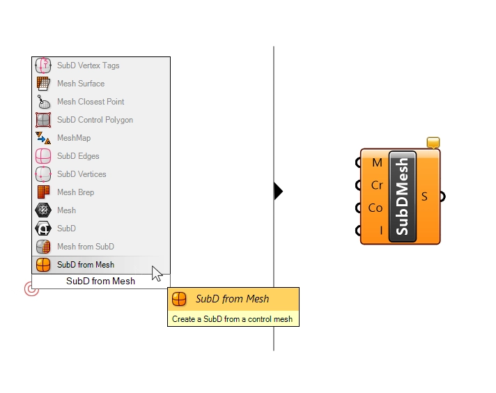
Let’s connect our Quad Remesh output to the ‘M’ input.
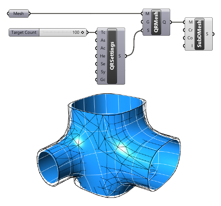
While the result is back to being a smooth geometry, it is now clearly much smaller than the original mesh!
Let’s fix that.
Step 4: Interpolating SubD
With the inputs of the ‘SubD from Mesh‘ component below the ‘M’, we can control how the mesh will be converted into a SubD.
Right-click on the ‘Cr’ and change the setting from ‘None’ to ‘At Mesh Edges’.
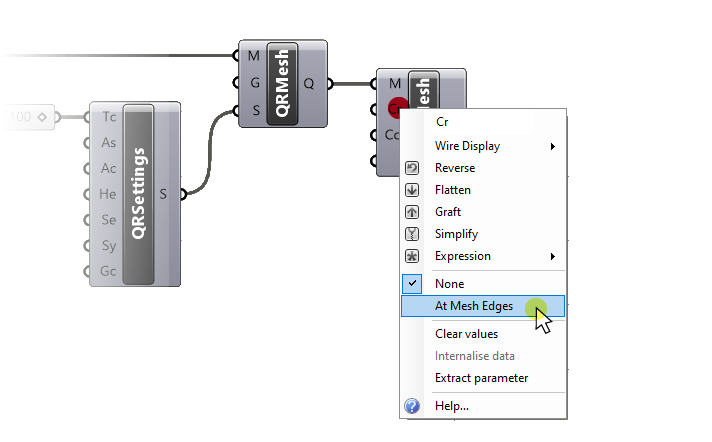
Repeat the same for the ‘Co’ input: activate the ‘At Mesh Corners‘ setting.
These two options will ensure that any mesh corners are retained as sharp corners instead of getting rounded in the conversion process.
The most important setting is the last one: the Interpolate setting. When active, the SubD will interpolate all the vertices of the mesh.
Think of it like the difference between a NURBS curve and the Interpolate Curve command: the Interpolate Curve command creates a curve that runs through every point we specify, as opposed to just using them as controlpoints, as the NURBS Curve command does.
It’s the same for this setting: we want the SubD to run through all the points or vertices of our simplified mesh.
Make sure to add a ‘Boolean Toggle‘ and set it to ‘True’. Alternatively, set the value inside the component directly.
Step 5: Final Conversion and Adjustments
The final step is to turn the SubD into a Brep, or polysurface. We’ll simply add a Brep data container component and plug in our SubD output.
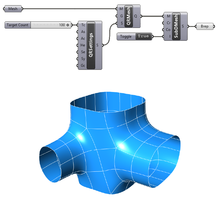
Our final result is a polysurface that reflects the original mesh while being made of much fewer segments.
At this point you can adjust the target count value of the ‘Quad Remesh Setting’ options, to find the best balance between precision and simplicity for your application.
Embracing the Challenge: Mesh to Polysurface Conversion in Grasshopper
As we conclude our exploration into process of converting a mesh to a polysurface in Grasshopper, it’s essential to highlight the importance of understanding and employing the appropriate technique for your specific needs. If a geometrically precise polysurface is your final goal, it’s best to model the polysurface from scratch. If approximations are sufficient for your use case, you can use one of the two different methods shown, each with its own strengths and weaknesses.
Our first approach – the ‘Mesh to Facetted Polysurface’ – focuses on maintaining the fidelity of the original mesh in its conversion to a NURBS geometry. This method ensures an identical copy, capturing every detail from the mesh, but with the inherent trade-off of increased computational cost and potentially cumbersome file sizes.
The alternative approach – ‘Mesh to Simplified Polysurface’ – gives us an avenue for producing a less complex and more manageable output. It does so by first simplifying the mesh and then converting it into a SubD before the final transformation into a polysurface. This method, although yielding a less precise copy of the original mesh, offers a more efficient and faster option for large meshes.
Choose the method that best fits your needs, and remember that the power of Grasshopper lies in its flexibility!
Happy modeling!