Welcome to the comprehensive guide on Construction Planes in Grasshopper! If you’ve been searching for a clear, in-depth exploration of this essential aspect of 3D modelling, you’ve come to the right place. Whether you’re a seasoned pro or a beginner in the world of Rhino and Grasshopper, this guide is for you. It’s designed to help you understand and master the use of construction planes. From understanding Rhino’s coordinate system to creating your own custom construction planes in Grasshopper, we’ll cover it all.
So, if you’re ready to take your 3D modelling skills to the next level, let’s dive in!
Why Do We Need Construction Planes in Grasshopper?
When it comes to parametric modelling, precision and control are paramount. Construction planes in Grasshopper are the key to complete control. They are the invisible guides that help us manipulate our 3D models with accuracy and ease.
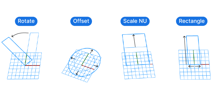
Commands such as Rotate, Scale NU, Project, Rectangle, and Offset, all rely on construction planes to function correctly. These planes provide a reference system that these commands use to perform their operations. For instance, when you rotate an object, the rotation is performed along an axis and location that is defined by the construction plane. Similarly, when you scale an object, the scaling is performed in relation to the construction plane.
By default, Grasshopper tries to “guess” which planes should be used for these and other commands. If it can’t find a suitable plane, it falls back on the default World XY Plane.
Without specifying construction planes, we’re essentially giving away control over how our models are manipulated. We’re leaving it up to Grasshopper to decide how to perform these operations, which can lead to unexpected or undesired results.
By using construction planes, we can regain this control. We can define our own reference systems that align with our models and our needs. This allows us to manipulate our models in a more intuitive and precise way.
In essence, construction planes in Grasshopper are the foundations upon which we build and manipulate our 3D models. They give us the control we need to bring our designs to life in the way we envision.
Understanding Rhino’s Coordinate System
Before we dive into the creating our very own custom construction planes in Grasshopper, let’s learn about Rhino’s coordinate system.
Every 3D modelling software is based on the fundamental space of geometry, called ‘Euclidean space’.
Think of this virtual 3D space as an infinite 3-dimensional canvas where you can design and place your 3D models. In this vast site, you have the freedom to move in any direction – horizontally, in depth, and vertically. These directions are our three dimensions, known as X, Y, and Z.
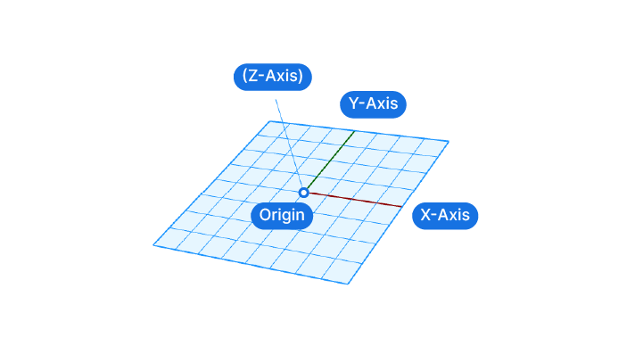
While this space is virtually infinite, it has a center, which Rhino calls ‘Origin’.
Now if we create a point in this 3D space, it’s location within this 3D space can be expressed using coordinates – numbers that indicate how far along the X (width), Y (length), and Z (height) dimensions the point is.
The numbers describe the X,Y and Z location of the point in relation to the Origin, which has the coordinates {0, 0, 0}.
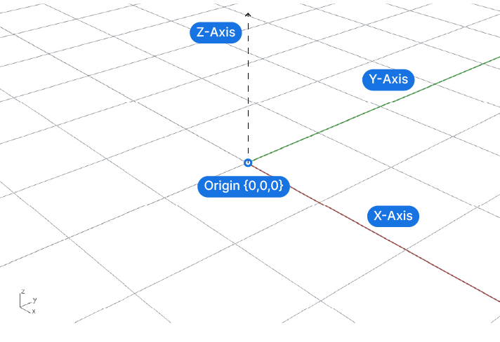
In Rhino, this fundamental space of geometry is called ‘World Coordinate System’. This global construction plane is the universal reference for everything we’ll create within Rhino and Grasshopper. The World Coordinate System is fixed an unchangeable.
Understanding Local Construction Planes
Now while the world coordinate system is a great way for Rhino to keep track of the precise location of objects, it is not very user friendly. The reason is that when we are building 3D models, it is easier for us to modify and manipulate objects in relation to the object itself rather than the world coordinate system.
This is where “Construction Planes” come in. We can think of construction planes as local coordinate systems that we can use to describe our geometric operations more intuitively.
For example, when we are rotating an object around the origin of the world coordinate system, it’s easy for us to describe the rotation as a 45 degree rotation.
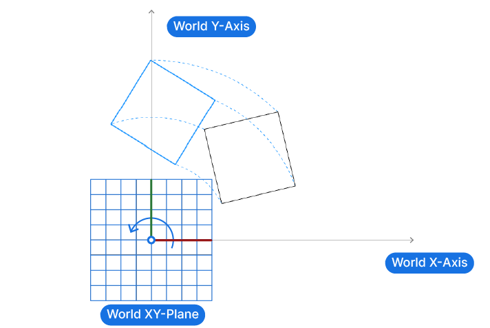
But if we want to rotate it around a point of our choice, for example one of its corners, its hard for us to describe the rotation in relation to the World XY-Plane.
Instead, its much easier to imagine a coordinate system located at our desired rotation point, aligned to our rectangle. Now, with this construction plane in place, its easy to define the rotation as simply 45 degrees in relation to the construction plane.
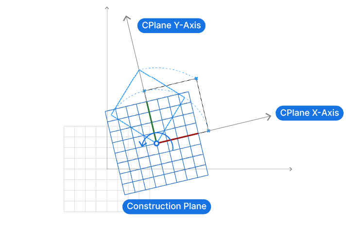
With construction planes, we can describe geometric operation in local, relative terms. This “localized” geometric transformation is far more natural for us to understand. Behind the scenes, Rhino will translate that “local” transformation into world coordinates.
Construction planes are really an aid for us to be able to modify geometry in a way that’s easy for us to control and understand.
In essence, construction planes in Rhino and Grasshopper serve as a bridge between the user’s intuitive understanding of object manipulation and the precise, absolute world coordinates that the software uses behind the scenes.
Elements of a Construction Plane in Rhino and Grasshopper
Before we create our own planes, let’s understand their key components.
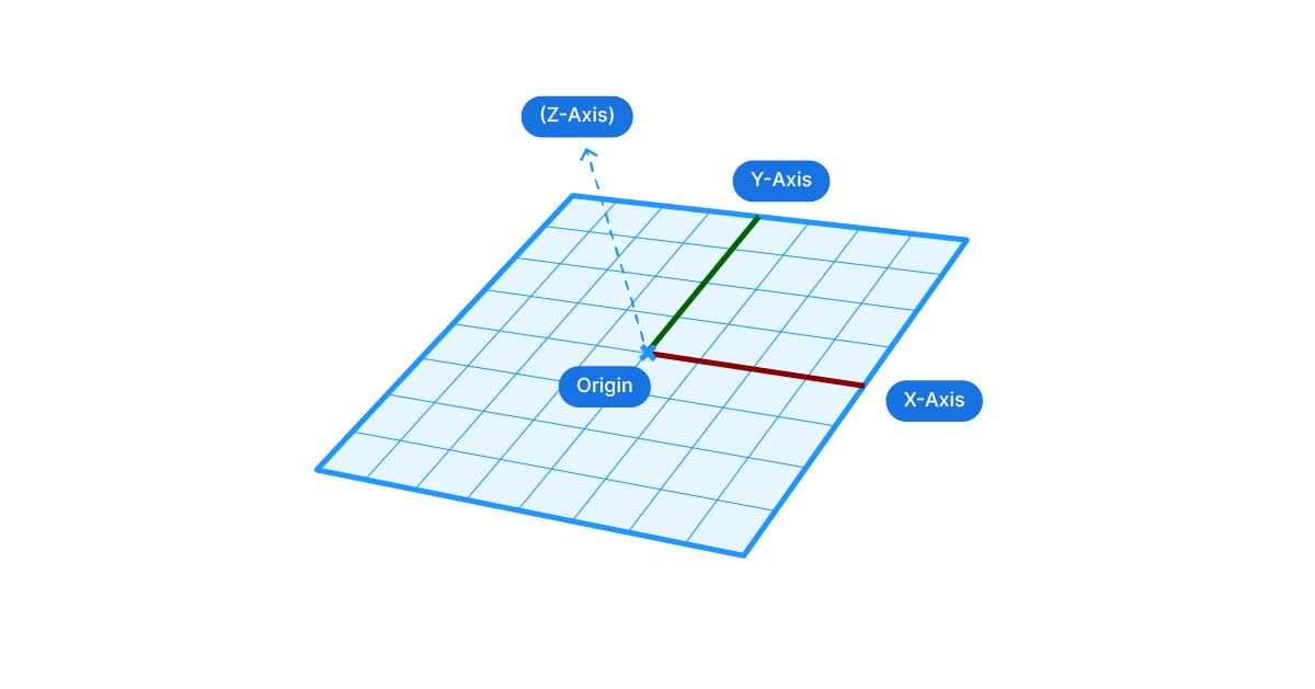
Construction planes are made of 4 elements: the origin the X,Y and Z axis.
In the viewport, construction planes are visualized with a grid and two colored axis. The red axis always represents the plane’s X-axis, and the green one the Y-axis. The Z-axis is never shown, more on that in a second.
The origin can be defined through a simple point. All we need are three X,Y,Z coordinates that describe the origin in relation to the world coordinate system.
The X,Y and Z axis are defined through vectors. These vectors specify the direction of each axis.
We can’t freely choose these three axes. By definition, they are all at a right angle (90 degrees) to each other.
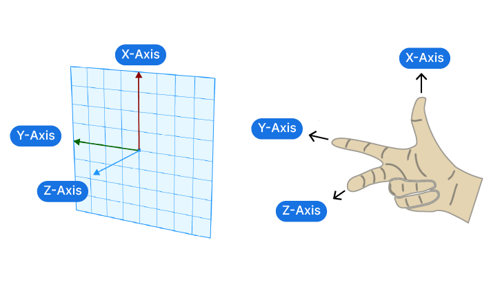
And in addition they follow the so-called “Right-hand rule“.
The Right-Hand Rule of Construction Planes
Stretch the thumb, index, and middle finger of your right hand so that they are all 90 degrees to each other. Your hand now describes the the relationship between the three axis. Now you may wonder how that is different from doing the same on the left hand? The difference is the direction of the third axis. Once you’ve defined two axis, the third could, in theory, point up or down from them, and still meet the 90 degree angle requirement. By convention, 3D coordinate systems always follow the right-hand rule when describing the X,Y,Z axis.
Here’s what this means in practice. When we create a construction plane in Rhino or Grasshopper, we can choose the first axis freely in 3D space.
Once the first axis is set with a vector, the second axis has one less dimension of freedom: it can only be rotated in a plane 90 degrees to the first axis.
Once this second vector is chosen, the third vector is already locked in place due to the right-hand rule!
Now it might seem complicated to manually specify the vectors in Grasshopper to define the axis, but luckily there are components making our lives easier.
Grasshopper’s default world plane components
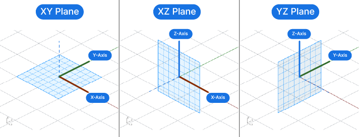
When we are creating a parametric model that is aligned to the world coordinate system, we can use Grasshopper’s pre-defined baseplanes. There are three baseplanes we can choose from:
The XY-Plane, the XZ-Plane and the YZ-Plane.
The two letters in their name describe two world axis that define the plane. The third axis is automatically set due to the right-hand rule.
To add them to your script, simply double-click on an empty spot on the Grasshopper canvas and type the letters of the two axis. Then select the component to drop it to the canvas.
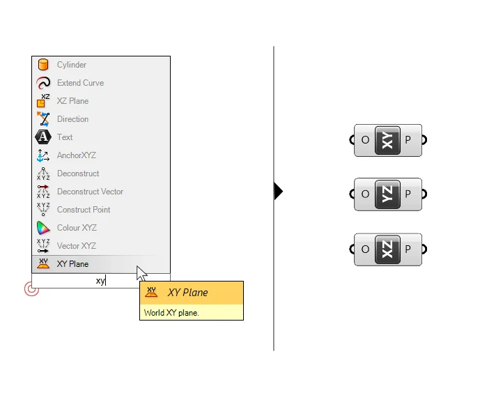
The baseplane components have a single input: the origin (O) of the plane. The origin can be specified with a point. The output is a construction plane located at the point specified, with axis pointing in the directions in their name.
Among the three, the XY-Plane is perhaps the most useful, as it describes a flat, horizontal plane. It can be used for any geometric operation we want to occur within this plane.
Creating a custom construction plane in Grasshopper
In many cases, we’ll want to create our own custom construction planes in Grasshopper. The component to do so is called ‘Construct Plane’. Type the name into the component search bar and select it to add it to your script.
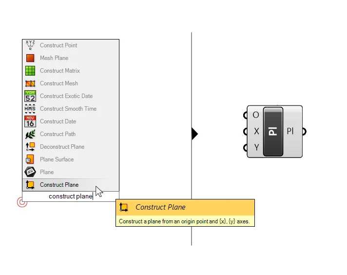
The component has three inputs: the origin of the construction plane, and the X and Y axis. We can define the origin with a point and the X and Y axis with vectors.
We can connect lines to the X and Y inputs as well, which is sometimes easier. Since a line, just like vectors, has a start point and a direction, Grasshopper will convert the line into a vector.
Here too, we can’t specify a Z-axis, because it will be determined by the orientation of the X- and Y-axis.
In the example below, I exploded a rectangle and used two of its edges to define the X and Y direction of the construction plane. The origin point is directly referenced from Rhino.
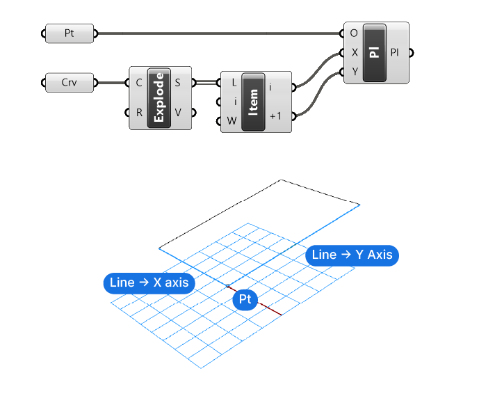
By default, the origin is set to the world coordinates {0,0,0} and the vectors to the world X and Y axis. Any input we provide will override these default values.
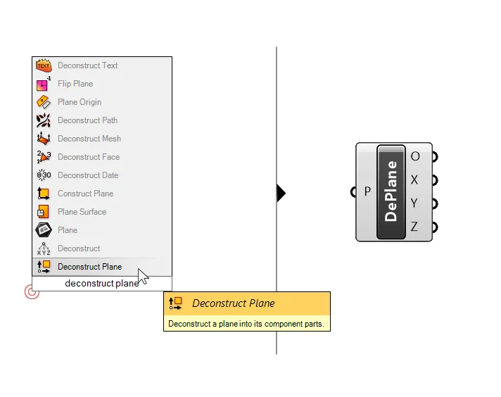
If we want to extract the axis vectors of an existing plane in our scripts, we can use the ‘Deconstruct Plane‘ component. Taking a plane as input, it will output the origin of the plane and all three of its axis as vectors.
This is particularly helpful when we want to use the ‘Z’ vector of a construction plane, to, for example, move an object in that direction.
Changing the origin of a plane in Grasshopper
In some cases we already have a plane, but it is not located where we need it. To change the origin of a plane in Grasshopper, we can use the ‘Plane Origin’ component.
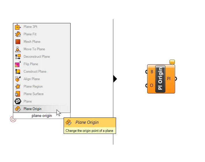
This component will take a plane (B for Baseplane) and a point (O for Origin) and output the plane with that point as the new origin.
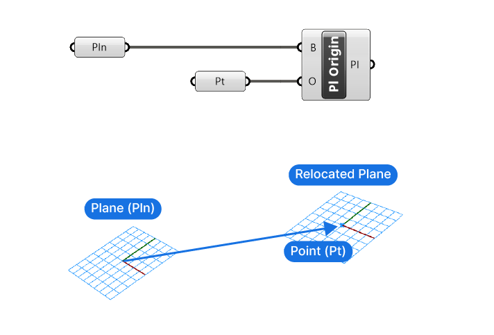
This component is often used for commands where the origin is important, such as rotations. We may have a plane we want to use for the rotation, but we also want to specify the rotation point. The Plane Origin will help us with that.
Generating Construction Planes from Curves
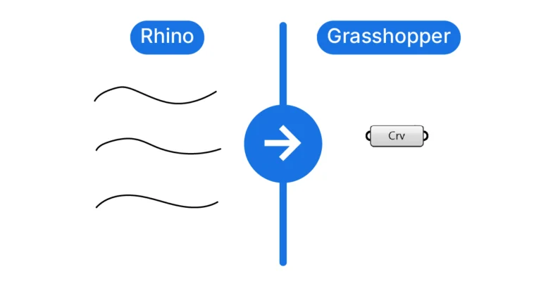
We don’t always have to define the construct planes ourselves, or use the world-oriented baseplanes. In Grasshopper we can extract and generate planes from other geometries, such as curves and surfaces.
Construction planes “extracted” from curves or surfaces are called “Frames” in Grasshopper.
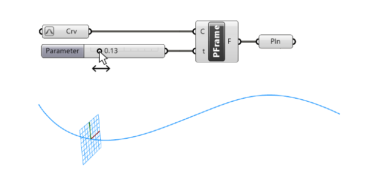
We can, for instance, generate Frames perpendicular to a curve, with the ‘Perp Frame’ component.
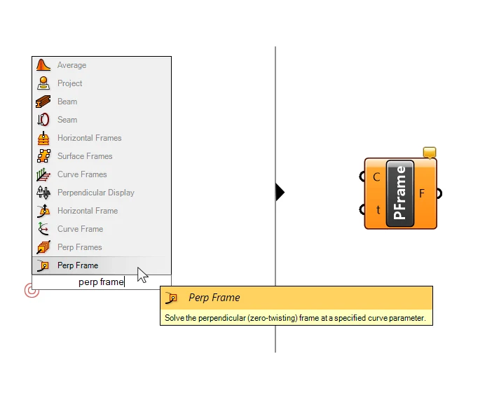
Given a curve and an Evaluation Parameter along that curve, the Perp Frame component will create a “Frame” or construction plane where the Z-Axis runs in direction of the curve.
To create several of these Frames along a curve, we can use the ‘Perp Frames’ (plural) component.
Instead of asking for the Curve Parameters at which to create the Frame, this component asks us to specify the number of frames to create along the curve.
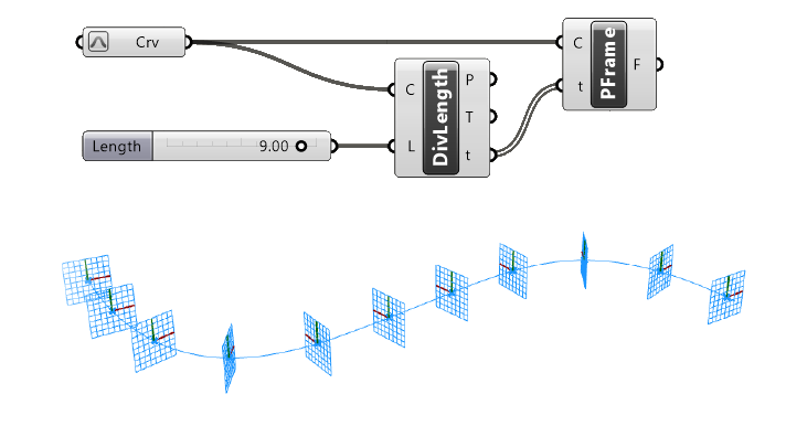
To have more control over the spacing and number of Frames (for example place them at a certain interval), it is recommended to use curve division components to divide the curve, and then use the Curve Parameters (t) to generate the ‘Perp Frame’.
Generating Construction Planes from Surfaces
When it comes to accurately placing and orienting geometry on a curved surfaces, it’s next to impossible to manually define construction planes. Luckily we can extract “Frames” or planes from any point on the surface.
To do so, all we need is the UV-Coordinate of the point on the surface. To extract the surface Frame at that point, we can use the ‘Evaluate Surface’ component.
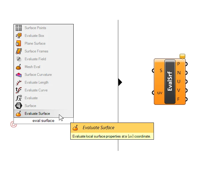
Much like the ‘Evaluate Curve’ component, which gives us more information about the curve at a point, the Evaluate Surface component outputs the point (P), the normal at that point (N), U and V values, and a Frame (F).
The Frame will automatically appear in the Rhino viewport.
In the example below I used a ‘MD Slider’ to generate a UV-value. I also reparametrized the Surface, to ensure the surface domain goes from 0 to 1 for both the U-and V direction.
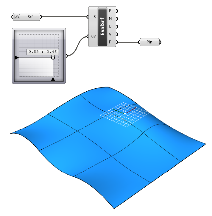
To generate multiple Frames, we can subdivide the surface to generate a grid of UV-values.
Final thoughts
And there you have it – a complete guide to construction planes in Grasshopper! We’ve journeyed from the fundamental concepts of Rhino’s coordinate system to the intricacies of creating and manipulating your own construction planes.
We’ve also delved into the practical aspects of generating construction planes with World Baseplanes, from curves and surfaces. With this knowledge, you’re now equipped to tackle complex 3D modelling tasks with greater ease and precision. Mastering construction planes is a game-changer in the world of 3D modelling in Grasshopper. So, keep practicing, keep exploring, and most importantly, keep creating!
Happy designing!