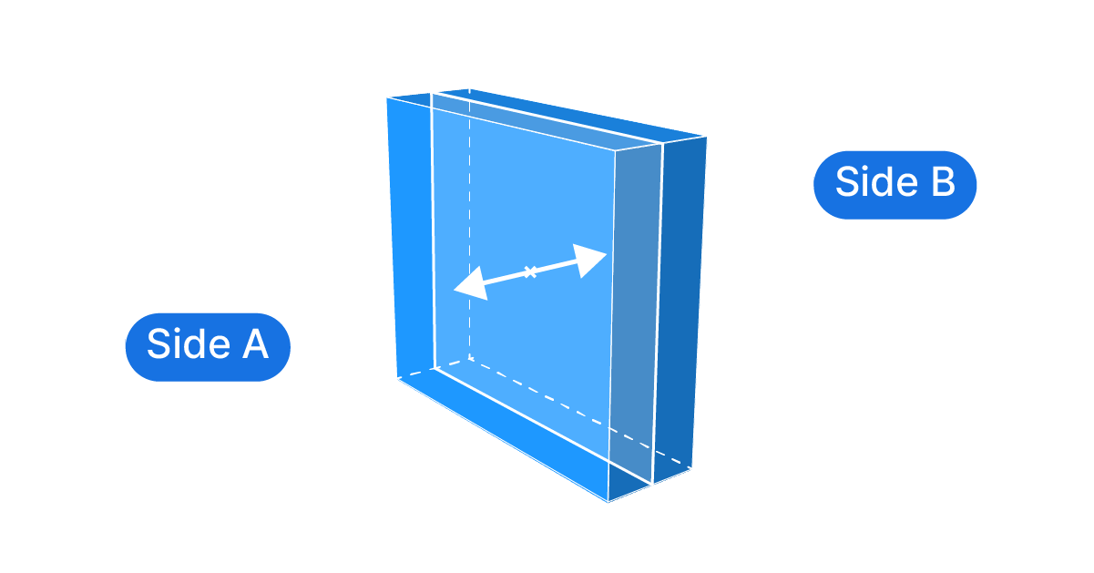
Extrusions are what brings the flat surfaces in our designs to life, but Grasshopper can only extrude in a single direction, so how can we extrude a surface to both sides?
Let’s dive in!
How to Extrude to Both Sides
Grasshopper doesn’t offer a component that would help us extrude a surface to both sides out of the box, so we have to create a small algorithm ourselves. Luckily this is really simple!
The way to extrude a surface to both sides involves two steps:
- Extruding the surface to the full total desired thickness
- Moving the resulting extrusion back in the negative extrusion direction by half the amount
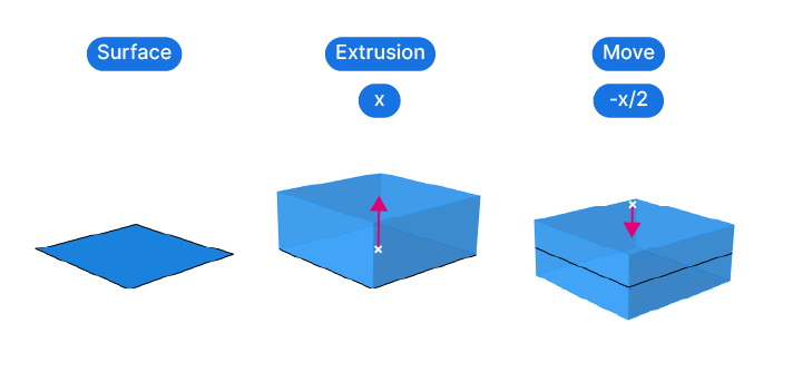
The crucial step is to define the extrusion vector. Once it’s defined, we can use a simple expression to invert the direction of the vector and half it.
Let’s see what this means in practice with an example:
Step-by-Step Tutorial
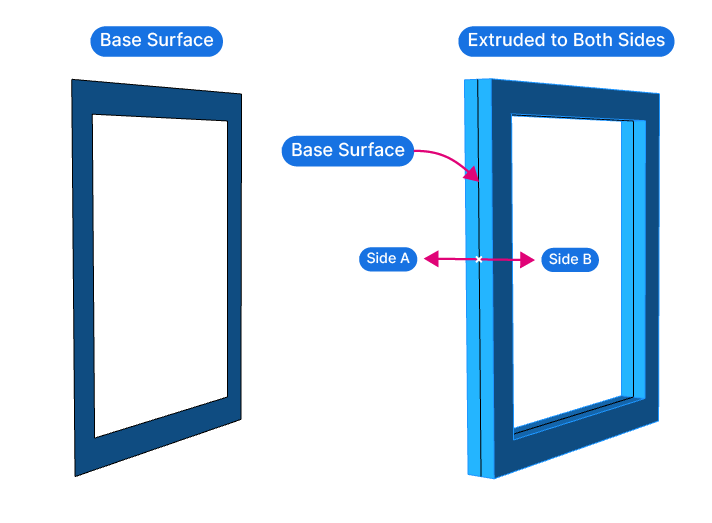
Let’s say we have a frame that we want to extrude to both sides.
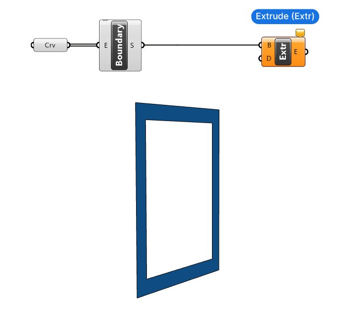
Basic Script Setup
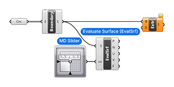
In this example, I referenced two curves from Rhino to a Curve container component, and then generated a surface from the curves using the ‘Boundary‘ component. The Boundary component does the equivalent of the ‘PlanarSrf‘ command in Rhino: it will process all the input curves and treats curves that are fully contained within another curve (in the same plane) as an opening.
Then let’s add an Extrude (Extr) component, and connect our surface.
Defining the Extrusion Direction
The Extrude component requires a Direction (D) input, which is a vector that defines the extrusion direction. If the surface is aligned with the x, y, or z axis, we can use the Unit X, Unit Y, or Unit Z components, that create predefined vectors for us. But in many cases the surface will be freely positioned in space, so we need a different approach.
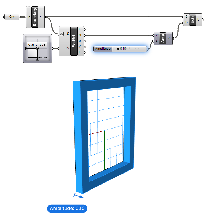
To get the normal direction of our surface, we’ll use the ‘Evaluate Surface’ component. This component allows us to evaluate a point on the surface by using its U-V coordinates. Besides the point, the component will also output the normal of the surface at that point. Since we’re dealing with a flat surface, any point on the surface will return the same normal direction.
To describe a coordinate on the surface, we can use the ‘MD-Slider’ component. MD stands for multi-dimensional. Compared to the Number Slider, which returns a single number, this component returns two numbers within two numerical domains. By sliding the dot in the center we can adjust the evaluation coordinates, but the default 0.5, 0.5 coordinates work just fine, as they correspond to the approximate center of the surface.
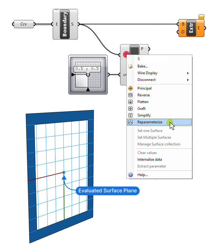
Just like curves, surface domains don’t necessarily come with a range of 0 to 1. To ensure the coordinates 0.5, 0.5 describe the middle of the surface, let’s right-click on the Surface (S) input of the Evaluate Surface component and click on ‘Reparameterize’.
Using the Surface Normal as Extrusion Vector
We get a preview of the evaluated surface plane in the viewport, located in the middle of the surface we want to extrude to both sides.
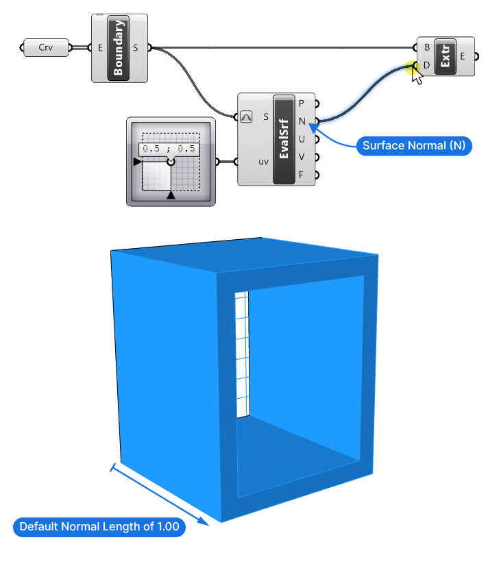
The Evaluate Surface component outputs several properties of the evaluated point: the point itself, the normal at that point, U and V -coordinates as well as the Surface Frame we see in the viewport.
We’re only interested in the Normal (N) in this example.
If we go ahead and connect it to the Direction (D) input of the Extrude component, we see an extrusion, but it has the default length of 1 unit. This is because the Normal is a vector, and vectors always come with a default length of 1.
Controlling the Extrusion Length
Let’s make sure we can control the extrusion length. We want to be able to use the direction the Surface Normal (N) is returning, but specify our own vector length. The length of a vector is called ‘Amplitude’ in Grasshopper. Let’s add the ‘Amplitude’ component to our script!
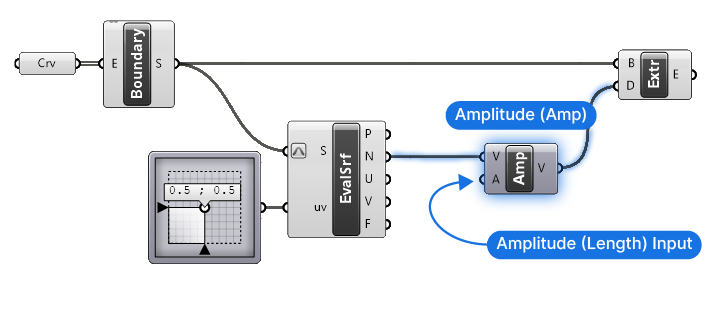
The Amplitude component has a Vector (V) input, and a Vector (V) output. The second Amplitude (A) input is where we can provide the desired length value of the vector.
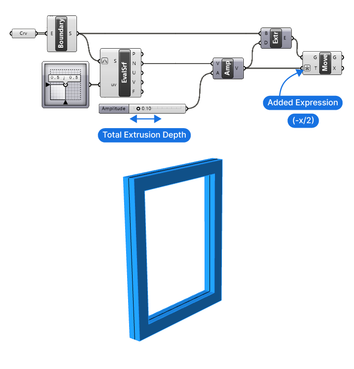
Let’s add a Number Slider to control the extrusion depth. We’ll specify the total extrusion length – including the depth of both sides.
The extrusion is complete! The next step is to move the extruded geometry back by half the extrusion amount.
Moving the Extrusion
Let’s start by adding a ‘Move’ component.
Just like the Extrude component, the Move component requires a vector that describes where to move the object. The input is called ‘Translation Vector (T)’. Both the Direction (D) and this Translation Vector (T) are simply vectors.
Let’s connect the Extrusion to the Geometry (G) input of the Move component and the same vector we created for the extrusion to the Translation Vector (T) input.
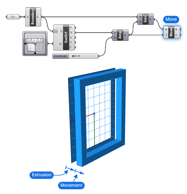
We are now moving the extruded geometry along the same vector, which moves the entire frame away from the original surface.
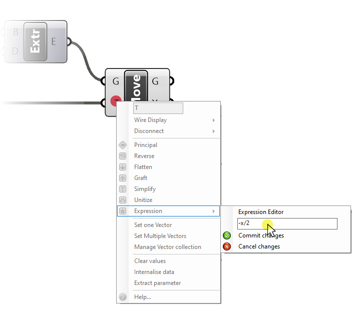
All we need to do now, is to invert the direction and half the length of the vector. To do so we simply right-click on the Translation Vector (T) input of the Move component, go to ‘Expression’, and type:
-x/2Into the expression field. Click ‘Commit Changes’ to confirm. Once complete, you should see a small asterisk sign right next to the input – this let’s us know that we’ve added an expression to this input.
That’s it! We can now adjust the Number Slider to control the extrusion depth, and Grasshopper will extrude the surface to both sides of the original surface!
Final thoughts
By combining basic Grasshopper components, we’ve unlocked a method to extrude a surface to both sides. While it may include a few extra steps, it also means that we gain more control. We can for example extrude the surface to both sides unevenly.
If you’ve found this helpful, check out Grasshopper Pro, our comprehensive online course tailored for architects and take your skills to the next level. Get all the essential algorithms and techniques you need to supercharge your design workflow!
Happy designing!