Welcome to this Grasshopper tutorial made especially for beginners. If you’re new to parametric design, you’ve come to the right place!
If you’re completely new to Grasshopper, make sure to start by understanding the core concepts of Visual Programming and read our in-depth introduction to the Grasshopper interface.
In this easy-to-follow tutorial, we’ll build a complete script following the Grasshopper Design Process. We’ll explain the logic used for the script, get to know a first set of key components like Move, Extrude, Rotate, and learn about vectors and number series.
Let’s dive in!
Our Project Goal: A Parametric Tower Design
To exemplify the core concepts of parametric design, we’ll build a simple script that creates a parametric tower made of stacked, rotated segments.
Every scripts starts with a clear idea of what we want to create. Here is our goal for this script:
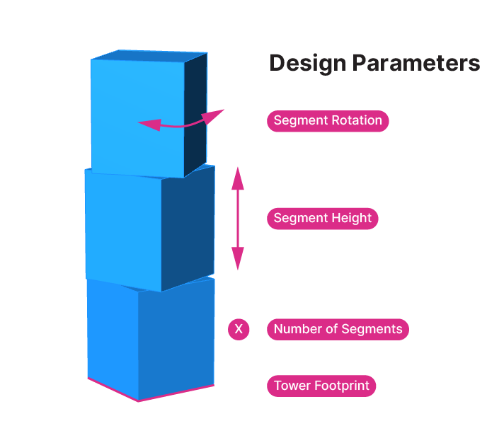
Our goal for this script is to create a model of a tower made of three sections, where each section has a different rotation. We want our parametric model to be set up so we can easily adjust the number of segments, their height, the footprint of the tower and the tower segments’ rotation.
Before we start adding components to our script, we need to take a moment to sketch out the design logic. In other words, we need to figure out a series of geometrical operations that will allow us to generate this form in Grasshopper.
Design Logic: The Blueprint for Our Script
There are many different ways to create this form, and the one below is just one of many. Here are the steps we’ll take to build our script:
- We will start by creating a circle. We’ll control the tower’s footprint by adjusting the circle’s radius.
- Next, we will divide the circle to get four points that we then connect with a NURBS Curve to create a base rectangle.
- Then we’ll generate a surface from the rectangle.
- Once we have the surface, we will move it vertically to three different heights.
- We are going to extrude the surfaces to create volumes.
- And finally we are going to rotate each of the volumes by a different amount.
Once the script is done, we can make adjustments at each of these steps to control and fine-tune our design.
Now that we’ve come up with a logic, let’s open Grasshopper and turn this logic into components!
Step by Step Tutorial in Grasshopper
Let’s start our Grasshopper tutorial by drawing a circle.
Let’s double-click onto the canvas to open the component search bar and type “circle” to find a suitable Grasshopper component.
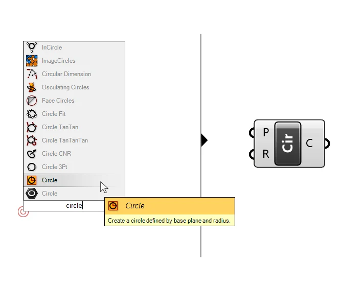
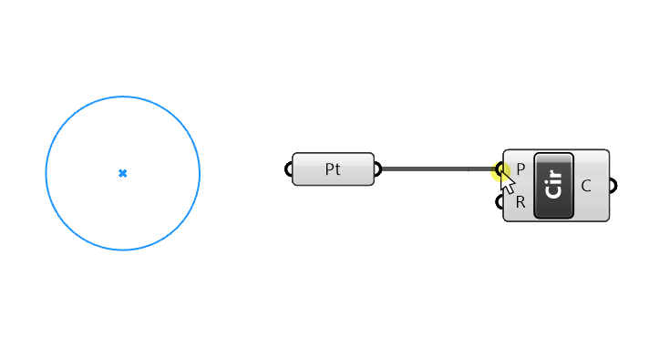
The first result is a data container, but it’s not the component we are looking for. We don’t want to just reference a circle from Rhino, we want to create a circle from scratch to be able to adjust its radius with a slider from within Grasshopper. If we hover over the second result, the tooltip says “Create a circle defined by base plane and radius“, that’s the one we want. Let’s click on it to drop it to the canvas.
The component has two inputs, the Baseplane (P) of the circle and its Radius (R). When we hover over the inputs we can see that both already have a default values: the Baseplane is set to “World XY”, which is the ground plane in Rhino located at the origin, and the radius has a default value of 1.
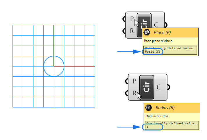
Since the component comes with default inputs, we already get a preview in the Rhino viewport. We see both the circle as well as the plane, shown as a grid.
Let’s make sure that we have complete control over the circle by referencing a point from Rhino as the baseplane and adding a Number Slider to control the radius.
Defining the Circle’s Baseplane
Let’s start by creating a point in Rhino. Next, we add a Point container component by typing “Point” in the component search bar and selecting the first result. Then we right-click on it, select “Set one Point”, and finally select our point in Rhino. Now we can connect the point to the Circle component’s Baseplane input. As a result, we can control the circle’s location by moving the point in Rhino.
Technically, a Point is not a base plane. A base plane is made of a point location as well as X and Y vectors that define the plane’s direction. But thanks to Grasshopper’s automatic data type conversion, if we just provide a point, it will be converted into a plane. Since we aren’t specifying X and Y vectors, Grasshopper will use the default Rhino X and Y direction for the orientation, resulting in a ground plane located at the point we referenced.
Adding a Number slider
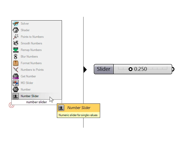
Next, let’s plug a Number Slider into the Radius (R) input to make it adjustable. Let’s type ‘number slider’ into the component search bar to add the component.
We’ll also change the Min and Max values to 1 and 20 respectively, and set the slider accuracy to 1, by double-clicking on the part of the component that says “Slider”, and adjusting the values in the window that pops up.
Let’s plug it into the Radius (R) input of the Circle component.
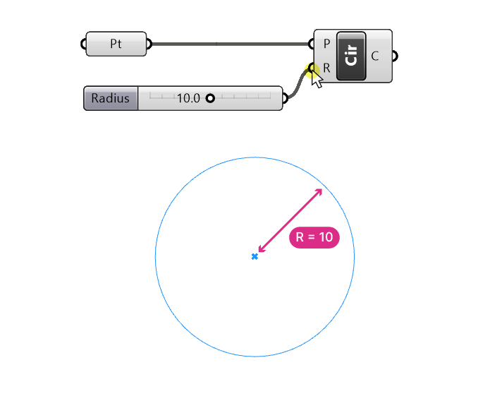
We can slide through the numbers and check in the preview if it works as expected. I will set the value to 10 for now.
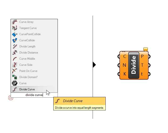
Dividing the Curve
Next, let’s use the Divide Curve component to generate four points along the circle.
Let’s connect our circle to the first input (C), which is the curve to divide.
We can see that the default 10 points have appeared on our curve.
Now let’s add another Number Slider to control the number of segments by typing “4” into the search bar, and hitting Enter. We get a slider with a range of 0 to 10 and the value set to 4.
Next, we can connect it to the Number of Segments (N) input of the divide component.
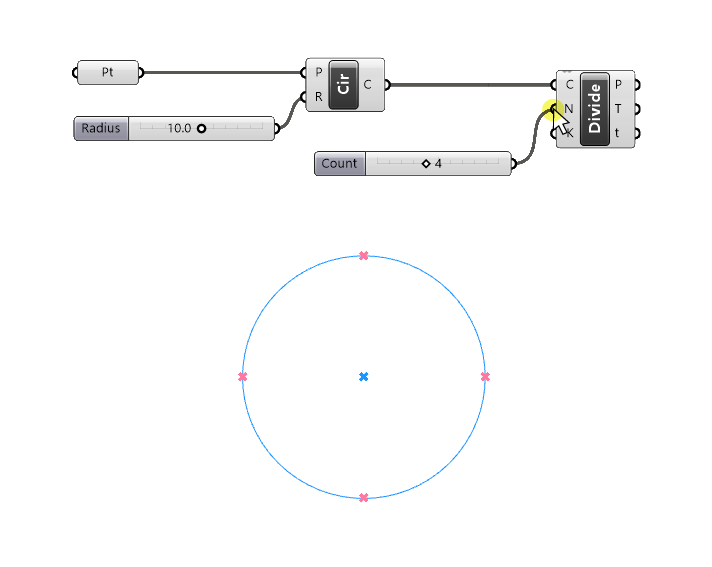
The preview in the viewport looks good: we get four equally spaced points along the curve.
Let’s take a look at the outputs of the component:
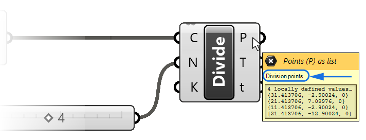
The first output P contains the four division points, that’s the one we are interested in.
Creating a NURBS Curve From Points
Next, let’s connect these four points to create a rectangle. In Rhino we create curves by defining its controlpoints with several clicks. In Grasshopper, we can’t select points in the viewport, so instead we need to create a list of points in the correct order and plug it into a curve component. All curves in Rhino are build on the same mathematical model: they are NURBS Curves. In Grasshopper, we can access the curve command through the “NURBS Curve” component.
Let’s type “NURBS Curve” and drop it on the canvas.
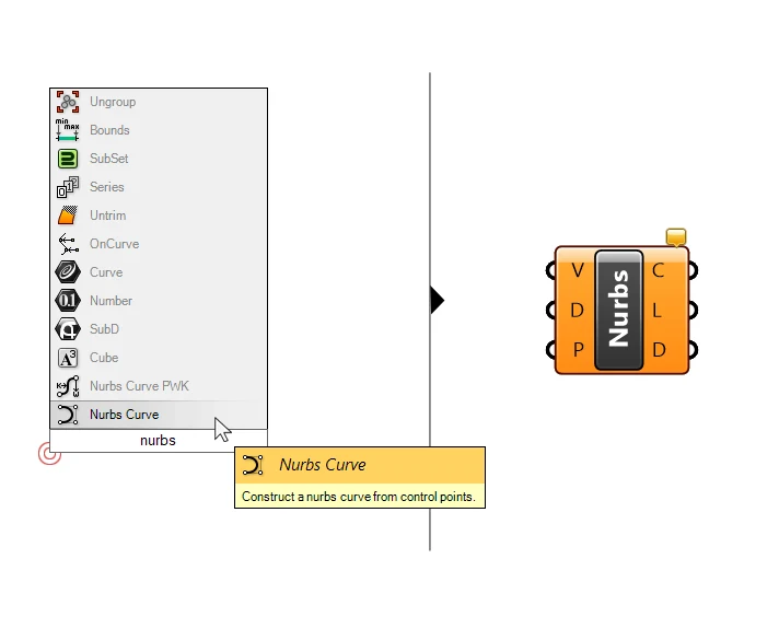
Let’s take a look at the inputs it requires. The first input asks for Vertices (V), which are the control points of the curve. Let’s connect our division points to this input. They are located in the “P” output of the Divide Curve component.
A look in the viewport shows that it’s not quite what we had in mind.
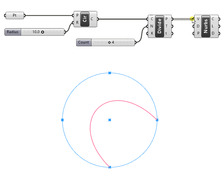
Let’s understand what’s going on.
First of all we notice that the curve is smooth instead of simply connecting the points.
This is because the default Curve Degree in the second input is set to “3”.
Understanding NURBS Curve Degrees
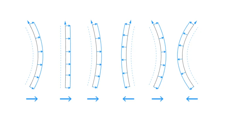
As we delve deeper into this tutorial, understanding how NURBS curve are constructed in Grasshopper is crucial. The curve degree of NURBS curves defines how smooth a curve is. It defines the continuity between the curve segments connecting the controlpoints. Think of it as controlling the relationship between the controlpoints and the resulting curve.
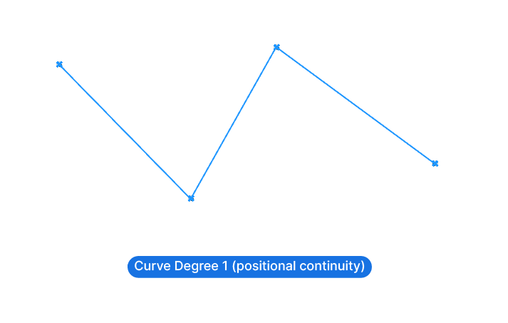
Degree 1
If the curve degree is 1, the controlpoints are connected with straight lines, creating a polygonal output. All curve segments meet in sharp corners, without any curvature. Two neighboring segments share one controlpoint, but all they share is its position. A NURBS curve with a degree of 1 has what’s called positional continuity.
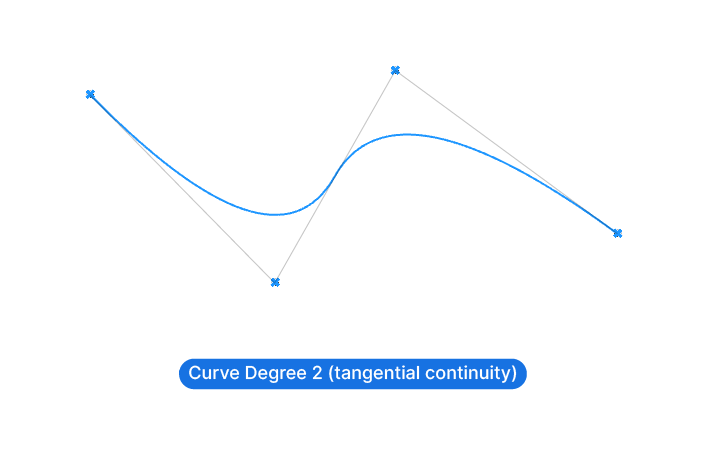
Degree 2
If the degree is 2, it means that the continuity is tangential. The resulting NURBS curve now flows in such a way that the curve segments connecting the controlpoints are tangents to the curve. The curvature now consideres 2 controlpoints to each side of a controlpoint to define the curvature.
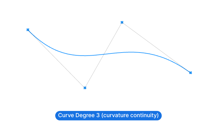
Degree 3
A NURBS Curve of degree 3 blends the curvature across three controlpoints at a time and appears the smoothest. In this case we have curvature continuity.
While there are even higher degrees than 3, there is no real reason to use them. In practice, we’ll be using either NURBS curves of degree 1 to create polylines, or NURBS curves of degree 3 to create smooth curves.
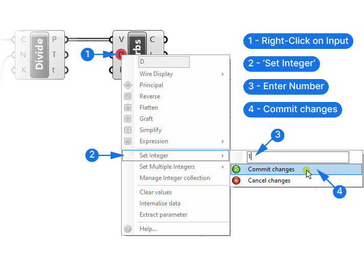
So if we want a polyline, we have to change the Curve degree to 1.
We could add a Number Slider once again, but since we are unlikely to change this value after setting it once, we can set the number inside the component directly. To do so, right-click on the Curve Degree input, go to Set Integer, and change the number to 1. Make sure to click Commit Changes to apply the change.
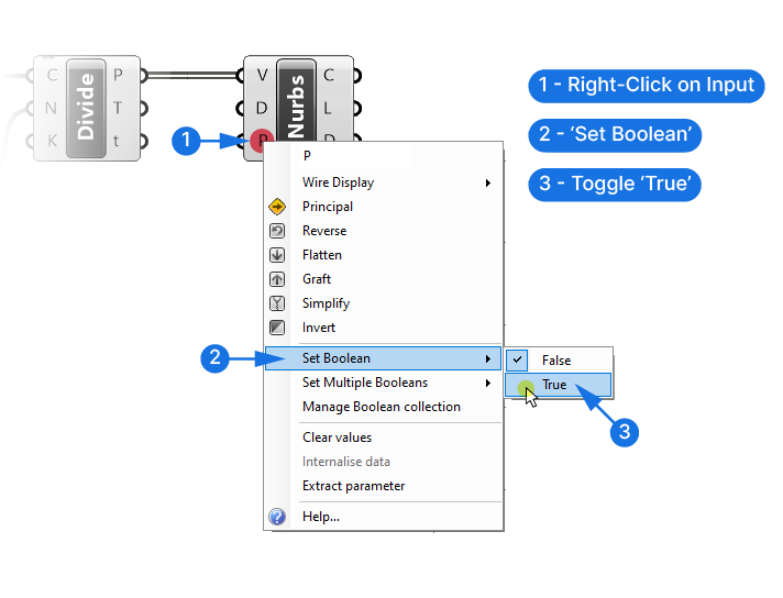
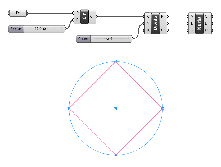
Our preview looks good. The only problem now is that the curve is not closed. The last input P of the NURBS Curve component defines whether the curve is periodic or not, or closed or not. The default is set to False, so let’s change it to True.
Once again let’s do this directly in the component as we won’t need to change this later. We right-click on the third input P, go to ‘Set Boolean‘ and change the value to True. Boolean is the term used to describe a value that is either True or False, or 1 or 0.
We now have our base rectangle ready!
Converting the Curve to a Surface
Next, let’s turn the closed curve into a Surface, by taking advantage of the automatic conversion functionality of Grasshopper’s data containers. Since we have a closed, planar curve, if we plug it into a Surface container, Grasshopper will convert it into a surface.
Let’s type “Surface” into the component search bar and add the surface container component.
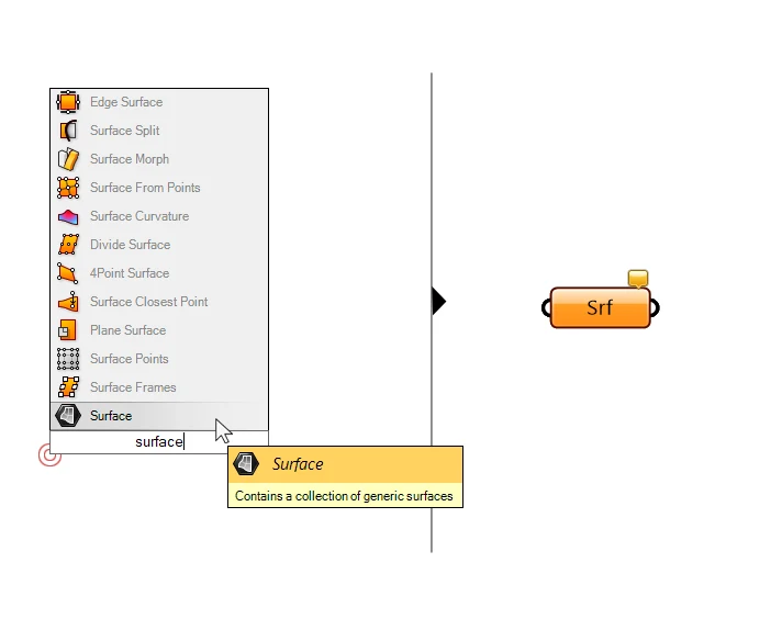
We can now connect the NURBS curve we generated. Again, we have several outputs for the NURBS Curve, but the one we need is the first output C, the ‘Resulting NURBS Curve’. Let’s connect it to the Surface container.
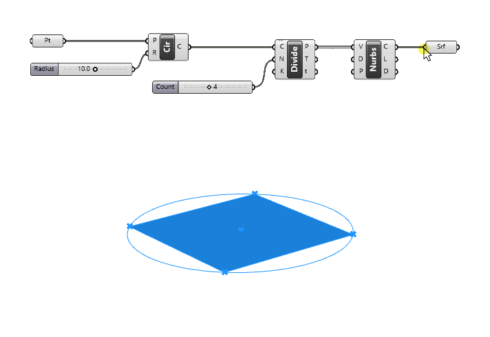
We can now see the shaded preview of the surface in the viewport.
Let’s switch to a perspective view to prepare for our next step: moving the surface to three different heights.
Moving the Surface
Let’s start with what we know: we need to move the surface, so let’s search for the move component in the search bar and click on it.
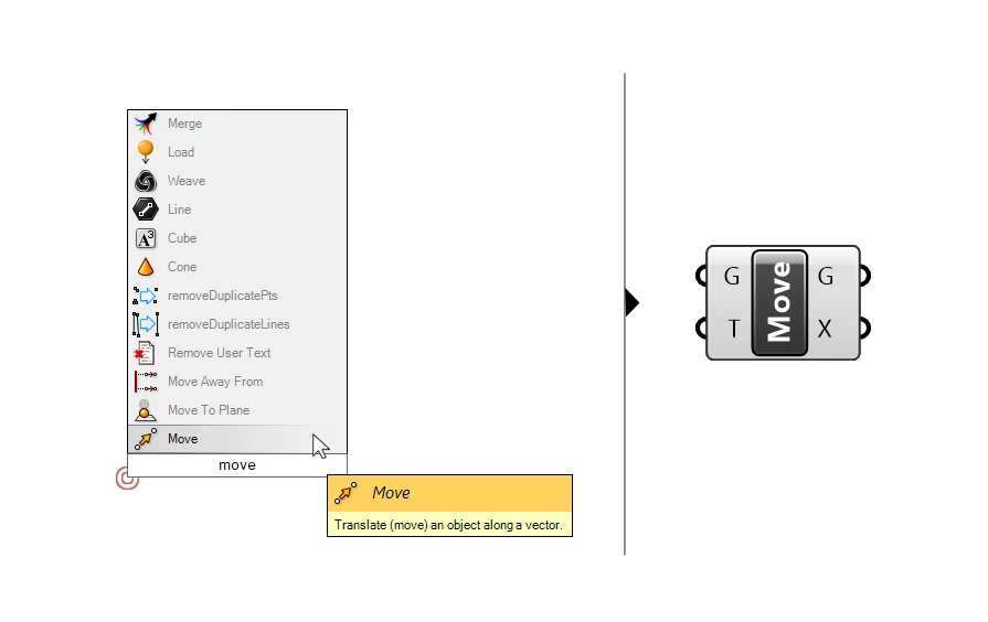
There are two inputs, the geometry (G) to move, and the translation vector (T).
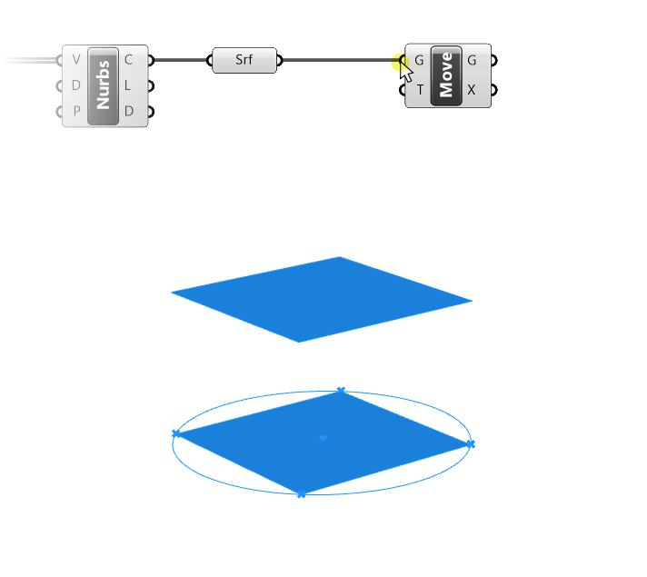
If we plug the Surface container output into the Geometry (G) input of the move component, we can see that the surface is already moved up. That’s because, once again, there is a default vector inside the translation vector input. We can see the vector by hovering over the translation vector (T) input.
It shows one locally defined value of:
{0,0,10} 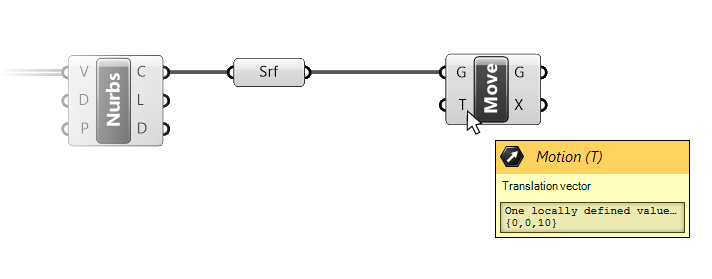
A vector is made of the three x,y,z-coordinates, just like a point.
{X-coordinate, Y-coordinate, Z-coordinate}The direction and length of the vector is defined as going from the origin {0,0,0} to the X,Y,Z coordinates specified. In Rhino, the Z-axis is the vertical axis, as shown in the little widget in the bottom left corner of the Rhino perspective viewport. The default vector of the Move component therefore describes a vertical movement of 10 units.
Let’s define our own vector!
Constructing a Vector in Grasshopper
In Grasshopper, there are several ways to create vectors. We can for instance, create a vector from scratch by defining X,Y, and Z values, with the Vector XYZ component. But in practice, we’ll rarely create vectors manually this way, because defining vectors just with X,Y,Z values is far from intuitive.
Often we simply want to move geometry along one of the principal axis: X, Y or Z. In our case we only want to move the surface vertically, along the Z-axis.
Unit Vectors
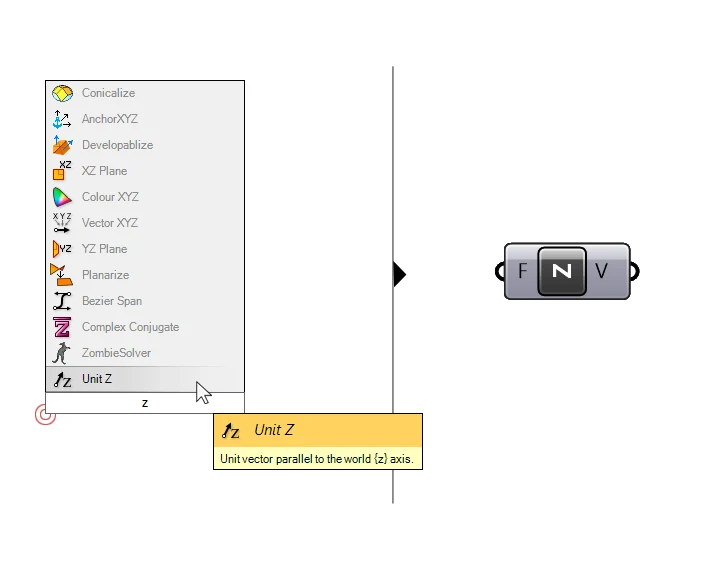
For that, Grasshopper offers three Unit vector components, one for each axis. Let’s add a Unit-Z base vector. Simply type ‘z‘ into the component search bar, and the “Unit Z” component should show up as the first result. Click on it to add it to the script.
The direction of this vector is locked to the Z direction. The way to control the length of the vector is by specifying it in the Factor (F) input of the component. Any number we connect will define the length of the vertical movement.
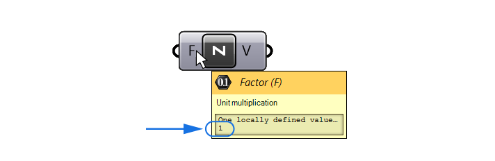
By hovering over the input, we see that it comes with a default value of 1. Meaning that this Unit Z vector describes a vertical movement of 1 unit upwards.
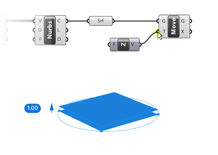
Let’s connect the Unit Z component to the translation vector input (T) of the move component. The preview in the viewport shows that the surface is now moved up by 1 unit.
Defining the Length of a Unit Vector
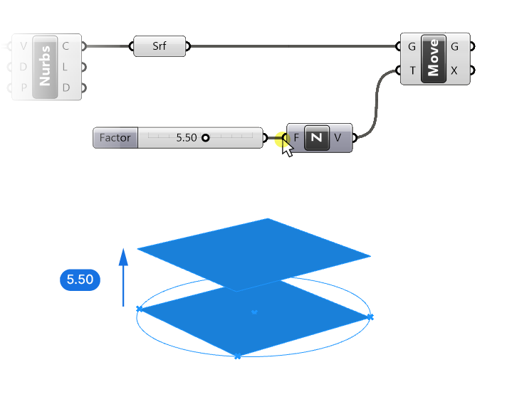
We can define the length of our translation vector by adding a Number Slider and connecting it to the Factor (F) input of the Z-Unit component. Once we do that, we have defined both the direction (along the Z axis) and the length of our vector.
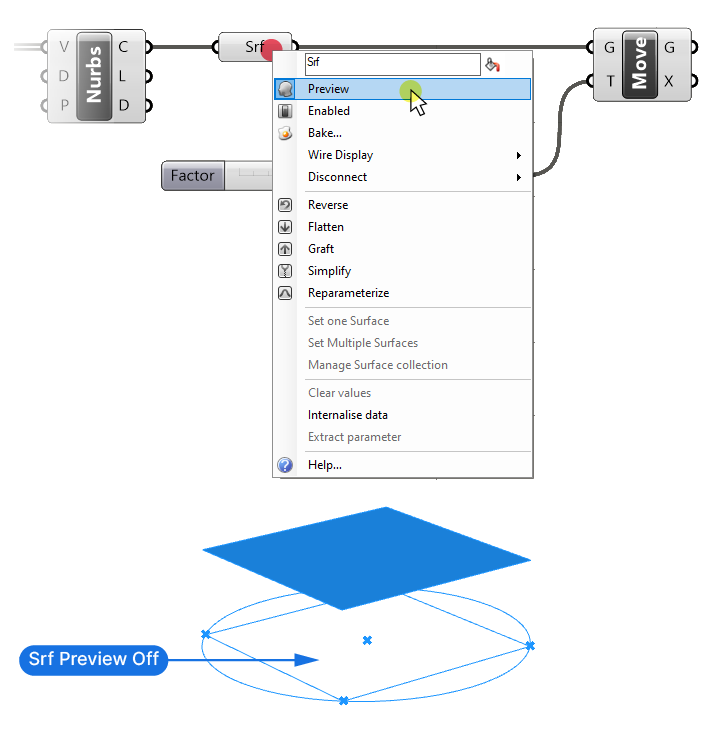
At this point you may be wondering why we still see the base surface on the ground level, even though we moved it vertically. The reason is simple: In Grasshopper, all component outputs exist at the same time. By using the Move component, we moved the surface vertically, but the original surface still lives, unchanged, in the Surface container. This is also the reason why there is no ‘Copy’ component in Grasshopper.
To hide the base surface, we can right-click on the Surface container component and toggle the Preview. The Surface component will turn dark gray and the surface on the ground plane will disappear.
We successfully moved the surface vertically by an amount we specified, using the Move and Unit Z components. To move it to three different heights, we need to connect three different vectors to the translation input of our move component.
Let’s do that next!
Generating a Series of Numbers
To move the surface to three different heights, we need three Z vectors:
- the ground surface can stay where it is, which means we move it by a value of 0.
- The second surface would be moved by a specified amount, let’s say, 10,
- and the third one by twice that amount, 20, to ensure that the segments are spaced equally.
This means we’ll need three numbers: 0, 10, 20.
We could add three sliders and plug them all into the F input of the Unit Z component to generate the three vectors. But then when we change one, we’d have to manually adjust the others to keep the equal spacing. Instead, we can describe the relationship between these numbers.
Mathematically speaking, we are creating a Series of numbers. We can use Grasshopper’s Series component to generate the numbers for us.
Let’s add it to the canvas by double-clicking onto the canvas and typing “series”, and adding the component by clicking on it.
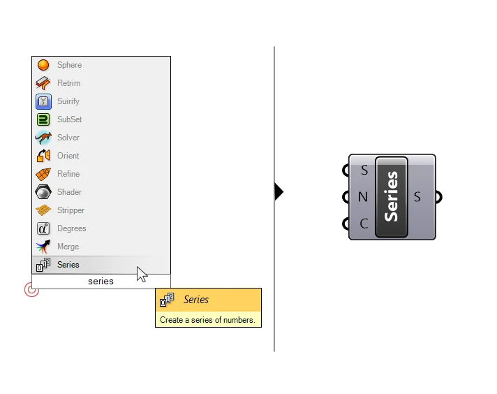
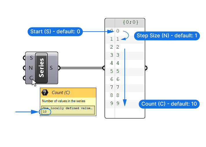
As the name suggests, the Series component creates a series of numbers. By checking the inputs we can see that it allows us to define
- the Start (S) or first number of the series,
- the Step size (N) for each successive number,
- and the Count (C) of the numbers to generate.
The default inputs are a starting point of 0, a step size of 1 and a count of 10, resulting in the following output:
0, 1, 2, 3, 4, 5, 6, 7, 8, 9
We can visualize the output by connecting it to a Panel component.
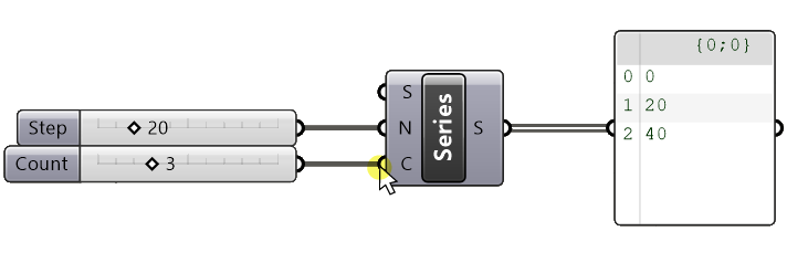
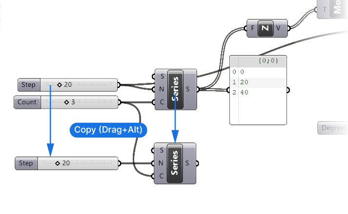
Let’s add two Number Sliders, one to define the Step size (N) and one to define the Count (C). We can leave the Start of the series at the default value of 0.
Let’s type 20 into the search bar and hit enter to add a number slider with a range from 0 to 100 and the value 20. And let’s do the same again with a value of 3.
Let’s connect the number sliders to the Series component.
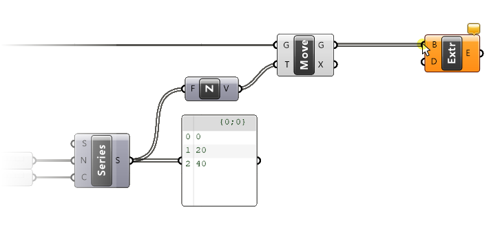
Checking the result in the Panel
We can see in the Panel that the numbers are what we expect them to be: the series starts at 0, has a step size of 20 and contains three numbers total.
Nothing has changed yet in our preview, because we still need to turn these numbers into vectors along the Z-axis. To do so, we connect the resulting series output (S) to the Factor (F) input of our Unit Z component. In doing so we’ll replace the existing connection to the slider, which we can now delete.
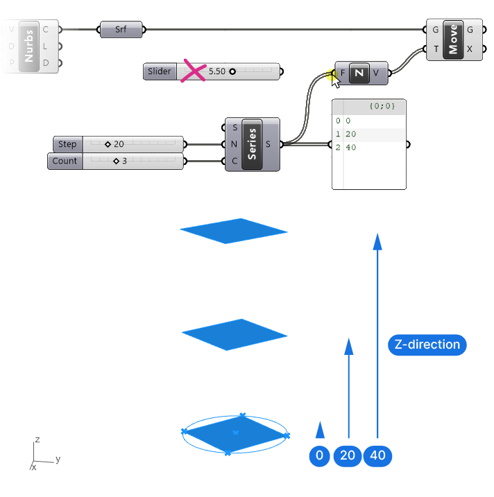
As soon as we do that, we can see our three resulting surfaces in the viewport. If we select the Move component, the surfaces are highlighted in the viewport. The first surface has been moved by a factor of 0 along the Z axis, so it’s still on the ground plane.
Next step: extruding the surfaces!
Extruding the surfaces
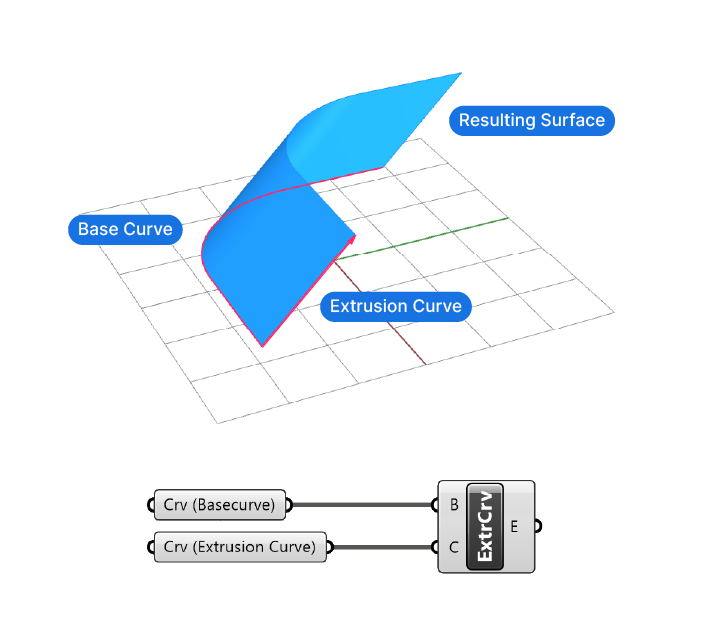
Let’s drop an Extrude component onto the canvas and check its inputs.
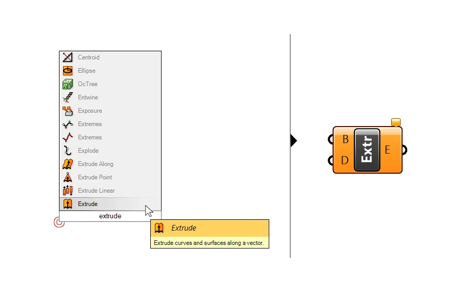
The Extrude component can extrude both curves and surfaces (B), and needs an extrusion direction (D) in form of a vector. Let’s go ahead and connect our surfaces.
Nothing happened in the viewport, because the extrusion direction input doesn’t come with a default value. Let’s set up the extrusion direction, which is once more vertical, or along the Z-axis. So let’s add another Unit Z component and connect it.
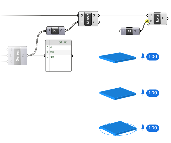
Our surfaces are now extruded by one unit, because, as we’ve seen before, the Unit Z Factor (F) input has a default value of 1.
To stack the tower segments, we need to extrude the surfaces vertically by the same amount as the distance between the moved surfaces, which is 20.
We could add another slider and give it a value of 20, but if we change the step value of our series later, we would need to also manually change this extrusion height.
Instead, we connect the same number slider we used to define the step size to the Factor (F) input of the Unit Z value for the extrusion. This way, these two values will always be linked.
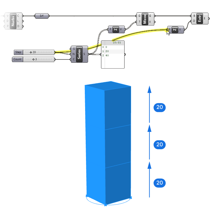
Perfect, we have our three extruded segments! The last step is to rotate the extrusions.
Rotating the Tower Segments
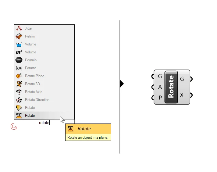
Let’s find the right component to rotate the tower segments. If we type “rotate” into the search bar, we get many results. Grasshopper has several components that can help us to rotate objects, they are all slightly different. Carefully read the popup descriptions to pick the right one.
We want the one that says “Rotate an object in a plane” – it’s the first result. Let’s select it.
You know the drill! Let’s check the inputs for the rotate component:
- The first input (G) is the geometry to be rotated.
- The second one (A) is the rotation angle. It’s important to note that the angle input must be in radians, not degrees. Luckily we can easily convert degrees to radians, I will show you how in a second. There is already a default value in here, 0.50 * Pi, which is the radians equivalent of 90 degrees.
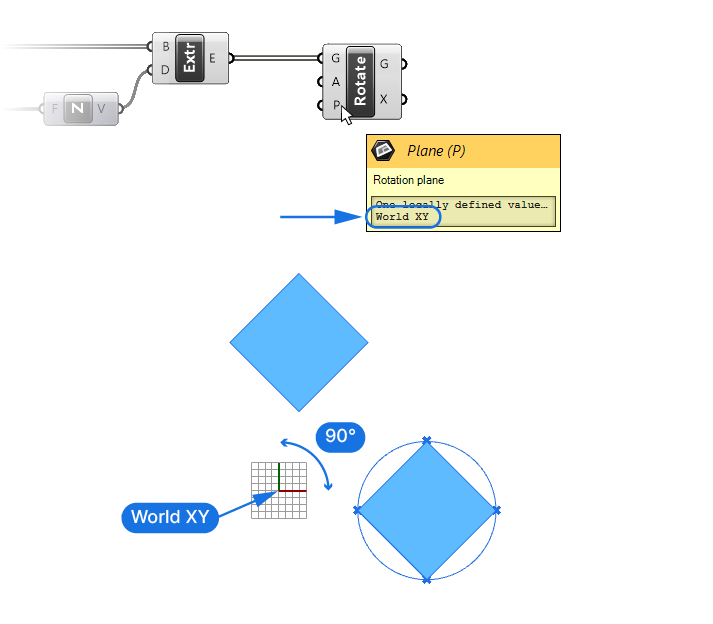
- The last input (P) is the rotation plane. When we rotate an object in a plane, the rotation plane defines both the location and rotation axis of the rotation.
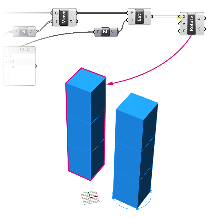
Let’s begin by connecting our extruded volumes output (E) to the Geometry (G) input of the Rotate component.
If we check in our viewport, we now have what looks like a copy of our tower in what seems a random place!
The reason is simple: let’s go to the top view to understand what happened.
Understanding the Rotate Component’s Default Inputs
Since we haven’t specified a rotation plane yet, the default rotation plane is the World XY Plane, which is the Rhino origin. That, combined with the default rotation input of 90 degrees, means that the component took our tower segments and simply rotated them 90 degrees around the origin. The exact location of the rotated segments depends on the location of the point in Rhino that we referenced the circle to.
Let’s specify the rotation plane to fix it.
Just like we did for the base plane of our circle, we can specify the base plane with a point. We want the rotation point for each segment to be the centerpoint of the segment.
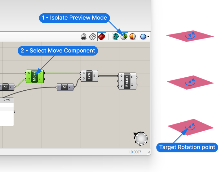
Let’s activate the isolate preview mode and select the Move component. This will only show the preview of the moved surfaces.
We want the rotation of the tower segments to happen around the center of each of these surfaces.
Finding the Center of a Surface
To find the center point of a curve or surface, we can use the Area component. Let’s add an Area component to our canvas and check out its inputs and outputs.
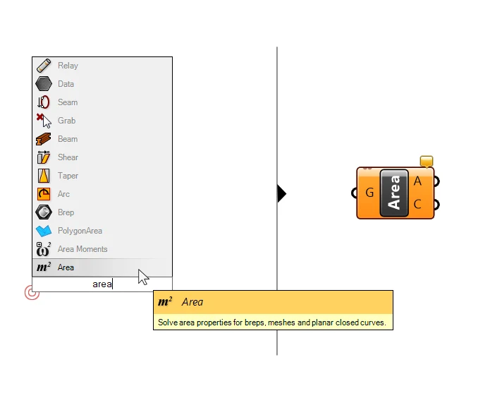
It accepts closed curves and surfaces, basically any closed, planar geometry as an input (G). The first output is the Area (A), a number, and the second one is the Centroid (C), the center of the input geometry.
Let’s plug our moved surfaces output into the Area component. When we select both, we can see the surfaces and the corresponding centerpoints.
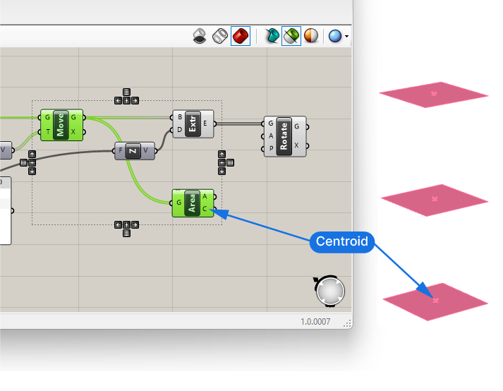
Let’s turn the isolate preview mode back off and connect the Centroids (C) to the Rotation Plane (P) input of the Rotate component.
If we now select our Rotate component, we can see that the preview lights up right on top of our existing extrusions. The rotation now occurs around the centerpoints of the tower. But since the geometry is rotated by the default 90 degrees, and we are dealing with a square, we don’t really see the rotation.
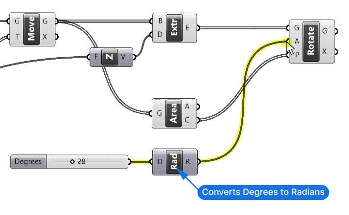
Controlling Rotation: Degree to Radians Conversion
Let’s solve that by specifying a custom rotation. We’ll add a Number Slider with the value of 45, by typing 45 into the search bar and hitting enter.
This will be our rotation angle (A) in degrees. Let’s connect it to the A input of the Rotate component. If we scroll through the Number Slider, the tower rotates erratically. That’s because while we are expecting the rotation to be in degrees, the Rotate component interpretates it as radians.
To convert the number we specify with the number slider to radians, we need a component that converts Degrees to Radians, it’s simply called Radians – let’s find it in the search bar.
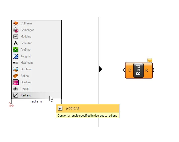
We can see from the description what it does: it converts an angle specified in degrees to radians.
Let’s connect the Number Slider to the degree (D) input and then the resulting radians angle to the Angle (A) input of the Rotate component.
The number slider value is now correctly converted to degrees and we can control the rotation correctly.
It’s hard to tell what’s going on in the preview because of the overlayed geometry. Let’s turn off the preview of the moved surfaces as well as the extrusions, so we just see the rotated segments. To do so, select the components and then hit Ctrl + Q to turn off the preview or right-click on each component individually and toggle “Preview” off.
We are now controlling the rotation of the tower with the number slider!
Rotating the Tower Segments
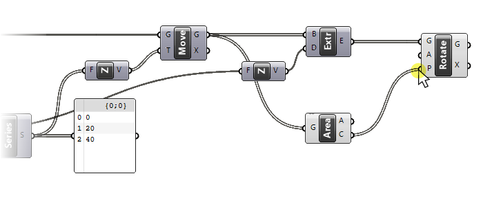
So, our rotation is set up, but at the moment all segments are rotated by the same amount. If we want to rotate each segment differently, we need to provide three different angles, one for each segment. Let’s use the Series component once more to create a series of numbers.
Instead of creating a new Series component, let’s copy the existing one, by dragging it and tapping ALT once, before letting go. When copying a component this way, all the inputs also remain connected. Let’s see which one we need to change.
We can keep the default starting value for the series of 0, and also the Count (C), which should match the number segments we create with the other series component, so we have as many rotation angles as we have segments. What we do want to change is the Step size (N) of the series. This is the number that will define the rotation. So let’s copy the “Step” slider and replace the Step (N) input of our new Series component.
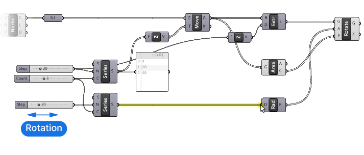
Now we can connect the output of this number series to the Degree (D) input of the Radians component. And remove the old number slider.
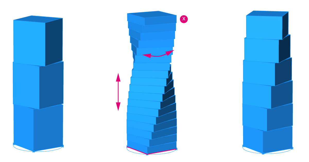
By adjusting the step size of our new Series component, we can specify the increment of the rotation angle of the tower segments. Adjusting this number will control the “twist” of the tower.
And here is the power of parametric design: We can now go back and change the values at every step of the script to tweak our design!
- By changing the radius of the circle, we change the overall footprint of the tower.
- The number of curve divisions defines the shape of our tower segments, a value of three will give us a triangular outline, and six a hexagonal shape and so on.
- We can then adjust the height of the tower segments, the count and the rotation with the Series inputs.
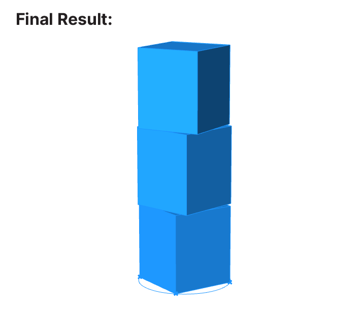
Experiment with the input values to see what kind of result you can achieve!
Once you are happy with the result, you can bake it by right-clicking the final component and selecting “Bake“.
Congratulations, you completed your first Grasshopper script!
How to Define the Starting Point of a Script
To reach this result, we don’t have to start with a point as we’ve done in this tutorial. We could directly reference a circle in Rhino instead of creating it in Grasshopper, or start the script with a referenced surface in Rhino.
The starting point of our Grasshopper script simply depends on which values we want to be able to change parametrically. If we are only interested in being able to adjust the rotation, we could start the script with the extruded volumes. In our example we have complete control over the design: from the location of the tower to its final rotation.
Conclusion
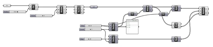
In this Grasshopper tutorial, we journeyed through the foundational elements of Grasshopper. Together, we’ve explored the power of the Series component, the intricacies of vectors, extrusion, rotation, and above all, the sheer adaptability of parametric design. What began as a simple concept in our minds has now manifested into a tangible design, showcasing Grasshopper’s transformative capabilities. Our final product, a customizable tower, exemplifies not only our achievements in this lesson but also the incredible flexibility of Grasshopper. The tower can be tweaked, reshaped, and reinvented with just a few simple adjustments.
Building on this foundation, I’d like to introduce you to my online course, Grasshopper Pro. Tailored for architects like you, this course dives deeper, unveiling more advanced features and techniques. We’ll explore intricate designs, enhance our problem-solving skills, and harness the full potential of Grasshopper. Whether you’re turning a dream project into reality or refining your architectural prowess, Grasshopper Pro offers the expertise to elevate your craft.
Happy designing!