If you come from modeling in Rhino, there’s nothing more natural than extruding a curve. But as soon as you try and do it in Grasshopper, you realize things look quite different! There are two main methods to extrude a curve in Grasshopper: extruding using vectors or using other curves. In this post, we’ll look at both methods using step-by-step instructions.
Let’s dive in!
Extruding a Curve Along a Vector
The Extrude component is one of the most basic but also most powerful components in Grasshopper. It allows us to turn curves into surfaces and surfaces into volumes, a key operation when fleshing out our scripts.
To add the Extrude component to the canvas, double-click into the empty Grasshopper canvas, type ‘Extrude‘, and click on the first result, at the bottom of the list.
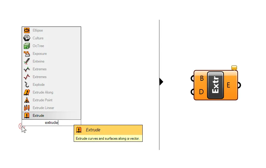
The component looks deceivingly simple. The first input B asks for the curve or surface to be extruded, and the second input D (from extrusion direction) for an extrusion vector.
To fully understand how the Extrude component works, we need to understand how vectors work. Here are the essentials:
Understanding Vectors in Grasshopper
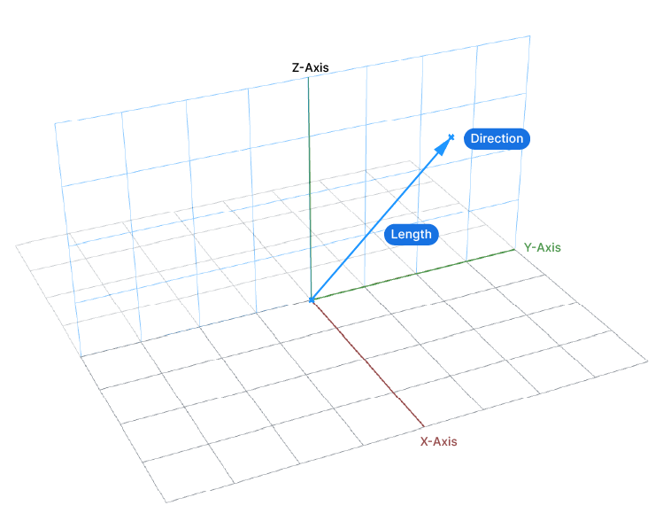
A vector has two essential properties:
- direction
- length
In Rhino we never encounter vectors. When we extrude or move objects, we define the movement with two clicks: one click at the starting point, where we want to move the object from, and one click at the endpoint, where we want the object to be moved to.
Rhino takes care of everything else and moves the object to the desired location.
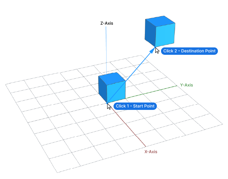
In essence, with our two clicks we are defining a vector: we are defining the direction by defining a start and endpoint and the length is the shortest distance between the two points.
Since we can’t interact with geometries directly in Grasshopper, we have to construct vectors to move and extrude curves.
We can create and manipulate vectors in a number of ways in Grasshopper:
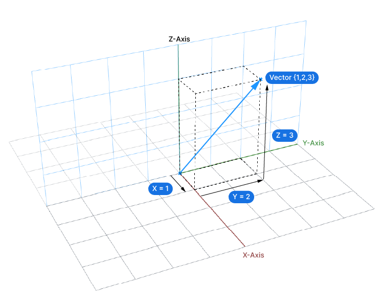
Defining a vector through X, Y and Z coordinates
By definition a vector can be described with three numbers: the X, Y and Z coordinates. These coordinates allow us to describe a direction in relation to the world origin. The origin will be the starting point of the vector, and the three coordinates will describe the location of the endpoint. As a result, we get both the direction as well as the length.
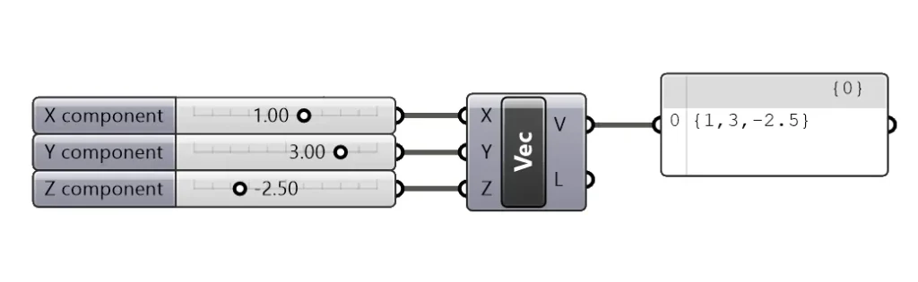
To add a X, Y, Z Vector component, double click onto the canvas and type ‘Vector XYZ‘.
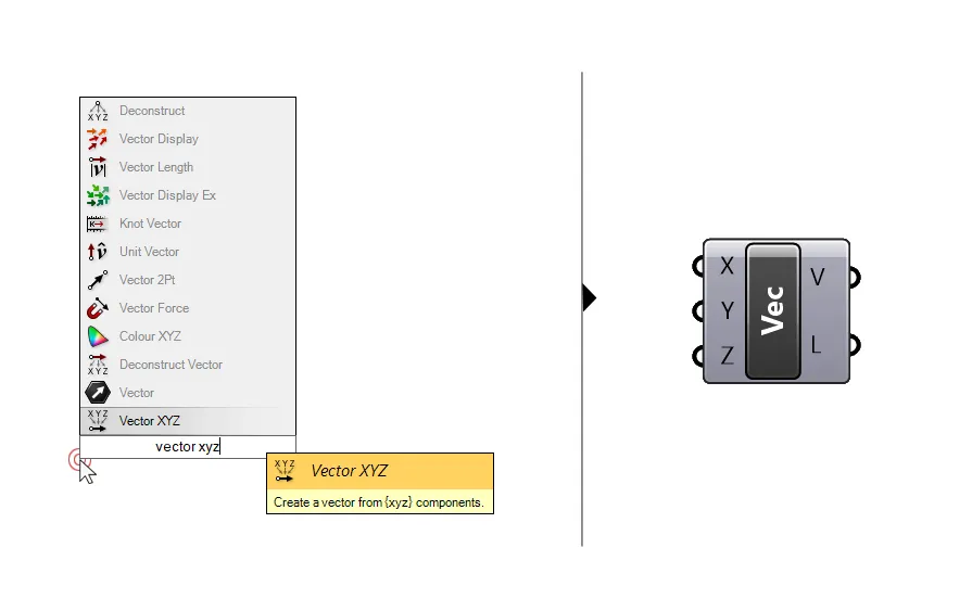
By specifying all three coordinates, for example with three separate Number Sliders, we can describe virtually any possible direction, since we can also use negative coordinate values.
While math enthusiasts may like this way of creating vectors, it is of little practical use when modeling in Grasshopper. 3D models are rarely completely aligned with the world coordinate system, and if they are not, figuring out the correct numbers to define a particular direction can get very complicated.
Another disadvantage of this method is that the length is purely a consequence of our three coordinates – it’s the distance from the origin to the point we are describing with our three coordinates.
Not very helpful if we want to control how far we want to move or extrude an object.
Using ‘readymade’ unit vectors
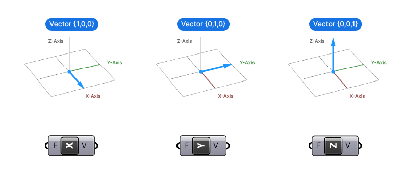
If we just want to extrude a curve along one of the main coordinate system axis, we can use unit vectors. We can add them to our script by double-clicking on the canvas and typing ‘Unit X’, ‘Unit Y’ or ‘Unit Z’.
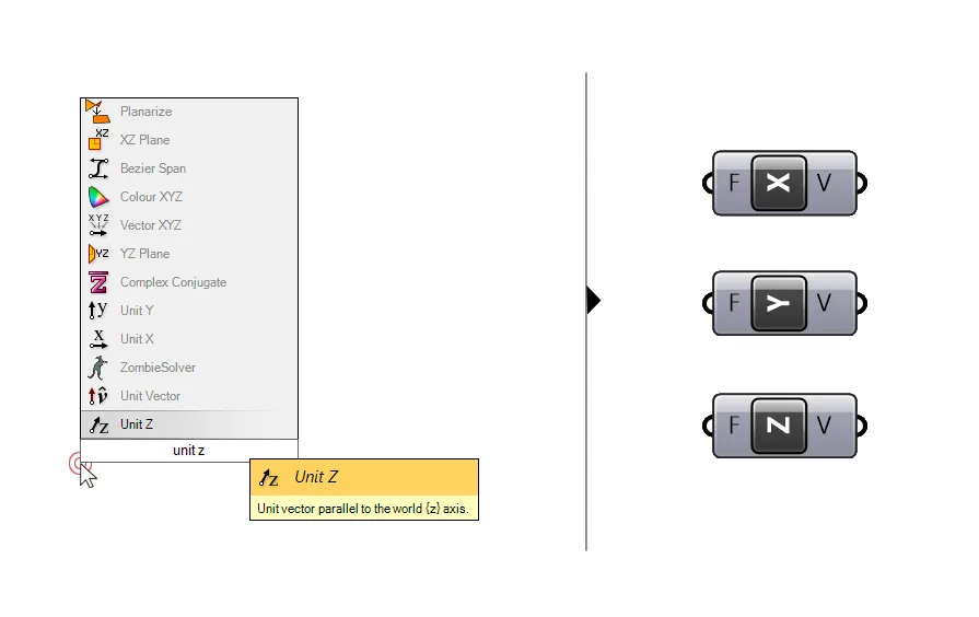
These ready-to-use vectors are vectors with a locked, predefined direction: they will point in the X, Y or Z direction respectively.
The only thing we can change is the length of the vector. We can define the length by providing a number to the only input the components have, called Factor (F). By default these unit vectors come with a length of 1. Any number we connect to the Factor (F) input will define the curve’s length.
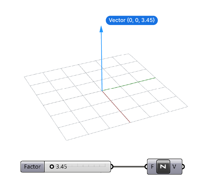
Using unit vectors to extrude curves in Grasshopper can be very useful when our models are aligned with the main coordinate system.
Regardless of the orientation, the Unit-Z component will be very useful anytime we want to extrude a curve vertically, whether it be up or down.
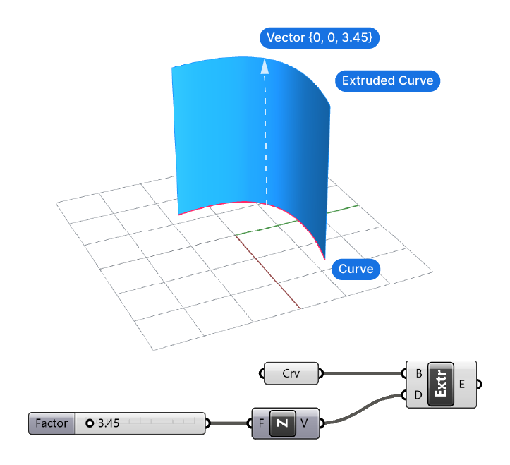
If we just want to extrude a curve vertically, using the Extrude component combined with the Unit-Z component and a number slider that defines the extrusion length, is the most effective way.
Defining a Vector with Two Points
Grasshopper offers a component that allows us to create a vector in the same way we would when moving objects in the Rhino viewport: by defining a start and an endpoint.
The component is called ‘Vector 2Pt’, type the name into the search bar to add it.
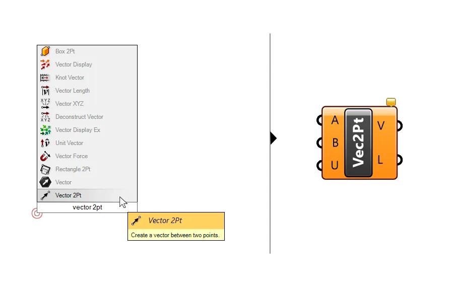
The component has three inputs: the first two are points. The first point will be the starting point, and the second the endpoint of the vector. The outputs are the resulting vector as well as the length of the resulting vector.
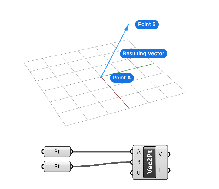
With third input ‘U’ which stands for unitize, we can reset the length of the vector to a length of 1, in the direction we specify with the two points. By default this option is set to ‘False’, we can right-click on the input, go to ‘Set Boolean’ and toggle the value there.
This way of defining vectors is one of the more intuitive, because it is similar to the way we define extrusions in Rhino.
Controlling Extrusion Length with the Amplitude Component
In most cases we want to extrude a curve along the direction of another curve in our Grasshopper script. But in many cases we are we still want to be able to specify our own extrusion length.
To do that we can use a component called ‘Amplitude‘. The name of the component refers to the fact that we can define the length (or amplitude) of a vector.
Simply type ‘Amplitude’ into the component search bar to find it and add it to the canvas.
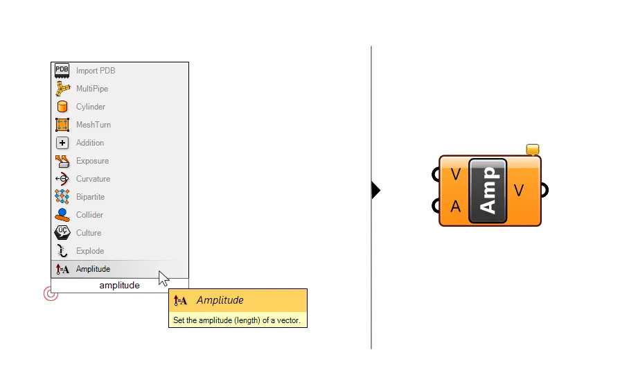
The component has two inputs: the vector to use for the direction and the amplitude or length we want our vector to be.
Here is where it gets interesting: for the vector defining the direction we can use any vector from the methods mentioned above, but we can also plug in any straight curve. The line is automatically converted into a vector by the component. This works because a straight line shares the same properties as vectors: it has a direction defined by the start and endpoint and a length.
Although the component won’t throw an error message if we provide a non-linear curve for the vector input, it will result in unpredictable outputs, so make sure to use straight lines only.
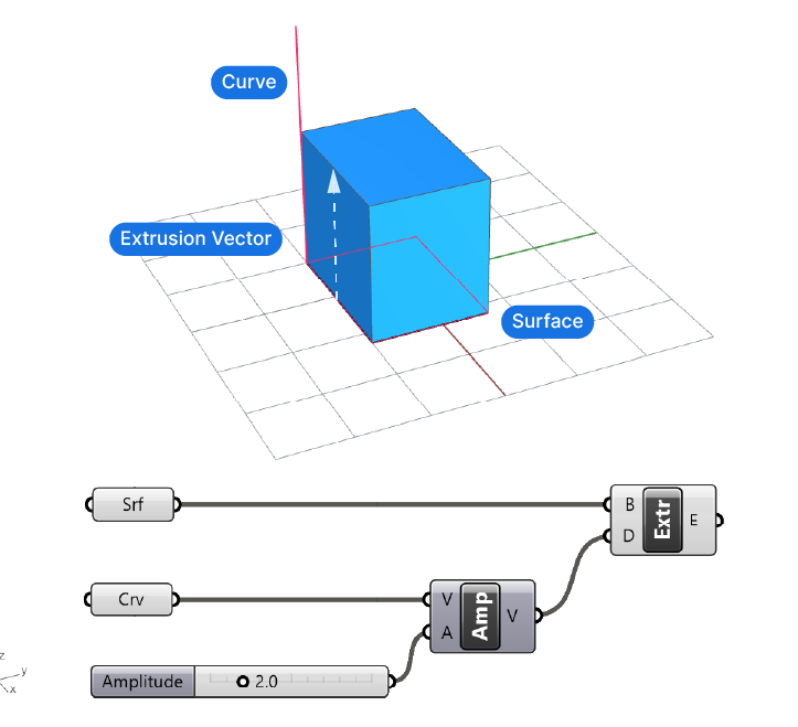
See a simple example below: In this example we have surface we want to extrude and a straight, vertical curve. Extruding a surface will lead to a polysurface or Brep. By feeding the curve into the first input of the Amplitude component we can specify the extrusion direction, and by adding a number slider to the second input, we specify the length of the extrusion in that direction.
Extrude Along Curve in Grasshopper
If we extrude a curve with a vector in Grasshopper, we’ll always be limited to straight extrusions due to the nature of vectors. If we want to extrude a curve with something other than a straight line, like a smooth curve, we can do that by extruding along another curve.
The component to do that is ‘Extrude Along‘. You can find it by double-clicking onto the blank canvas and typing its name.
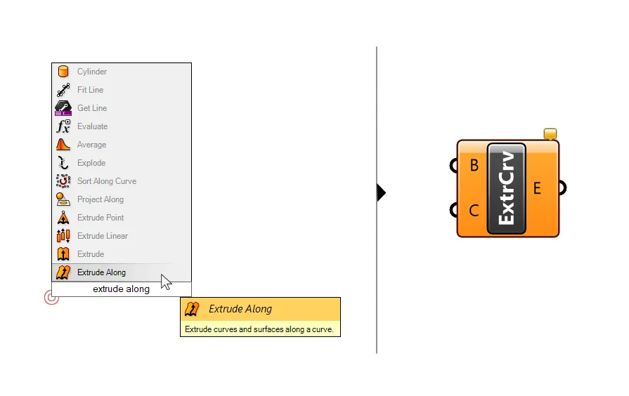
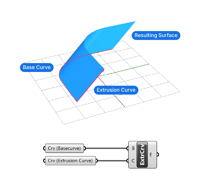
Much like its Rhino counterpart, this component will extrude a curve along another curve. The inputs are two:
- the curve to extrude
- and the curve to extrude along.
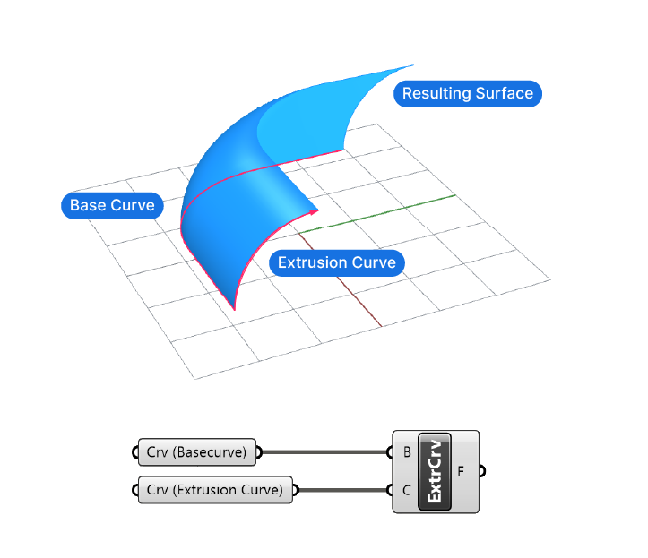
The order is important here: The focus is on the first input, the curve to be extruded. The second input, the extrusion curve can actually be anywhere in the document, it just describes the extrusion trajectory of the base curve, it will not be directly involved in the creation of the surface, like it would be in a loft for example.
I still recommend to place the extrusion curve at the beginning of the base curve, as shown in the example below. That way you’ll have an easier time controlling the result.
Always be aware of the curve direction of the extrusion curve to avoid unexpected results.
While this component does create a complex surface with just two curves, it does lack ways to fully control the output. In many cases, you can generate the same output with a combination of offsets and lofts, which gives you better control.
Concluding Thoughts
In conclusion, extruding a curve in Grasshopper is a crucial operation that allows you to turn curves into surfaces and surfaces into volumes. There are two ways to extrude a curve in Grasshopper, extruding with a vector or extruding with a curve. In both cases we can control the direction of the extrusion, the length and the extrusion trajectory.
By understanding the basics of vectors and using the right technique for your needs, you can easily achieve the desired result and take your modeling skills to the next level.
If you want to learn more about Grasshopper, check out Grasshopper Pro – our online course tailor-made for architects. The course will fast-track your learnings by teaching you the exact techniques the leading architecture firms world-wide use to create outstanding designs!
Happy designing!