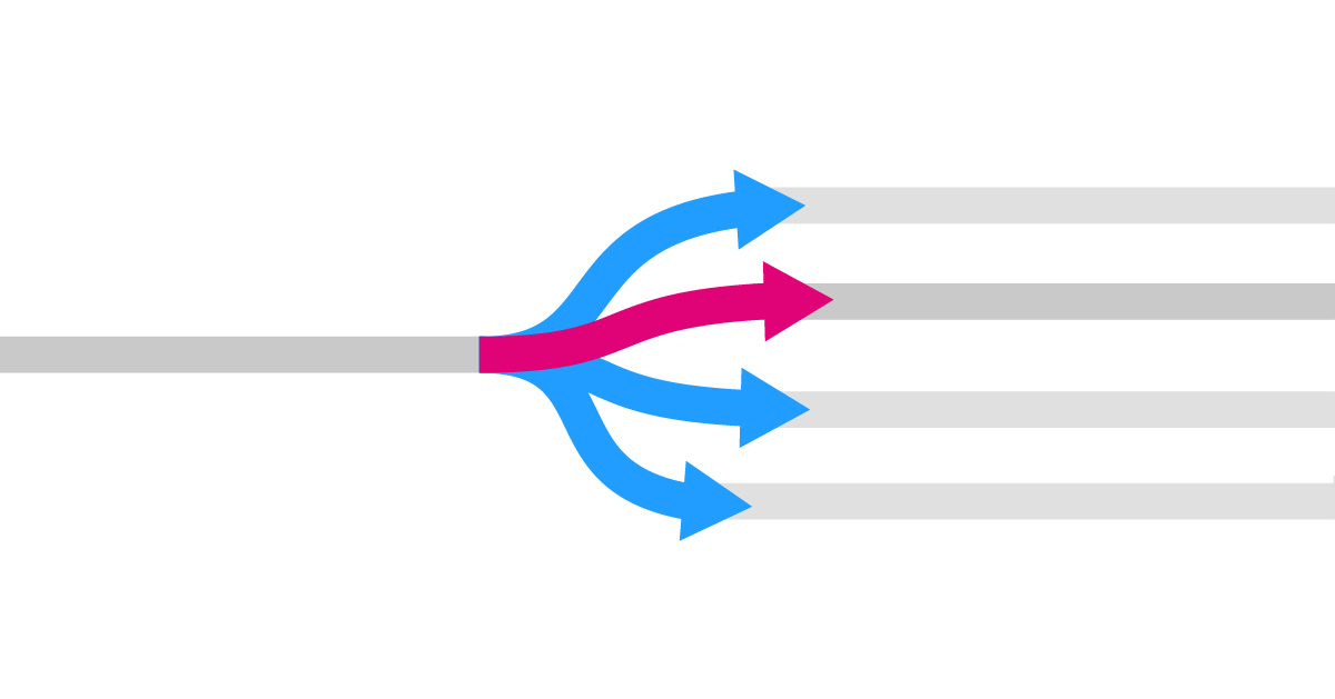
One key tool for managing data flows in Grasshopper is the Stream Gate component. The Stream Gate component allows you connect one input stream to multiple output streams, with a number controlling which of the outputs the data is directed to.
Understanding the Stream Gate Component
The Stream Gate component operates much like a logical ‘gate’. To understand how it works, let’s start with a simple analogy:
Imagine a railroad track. At a certain point, the tracks diverge, allowing a train to take either track A or track B. A gate, in this context, is the switch that controls which track the train will follow. The switch is absolute: the train either continues on track A or track B.
Similarly, the Stream Gate component controls the path of an entire data stream. Instead of manually disconnecting and connecting components to run different sections of your script, the Stream Gate automates this process, making it more efficient and user-friendly.
Adding the Stream Gate Component
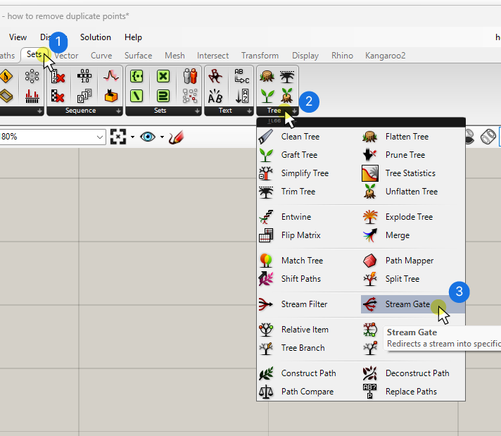
To begin, let’s add the Stream Gate component to our Grasshopper canvas. You can find it under the ‘Sets‘ component tab, grouped under ‘Tree‘.
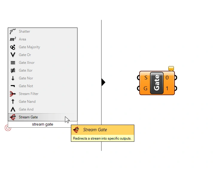
To add the component using the component search bar, double-click anywhere on the Grasshopper canvas and type ‘stream gate’, and click on the component.
Inputs and Outputs Explained
The Stream Gate component has two inputs:
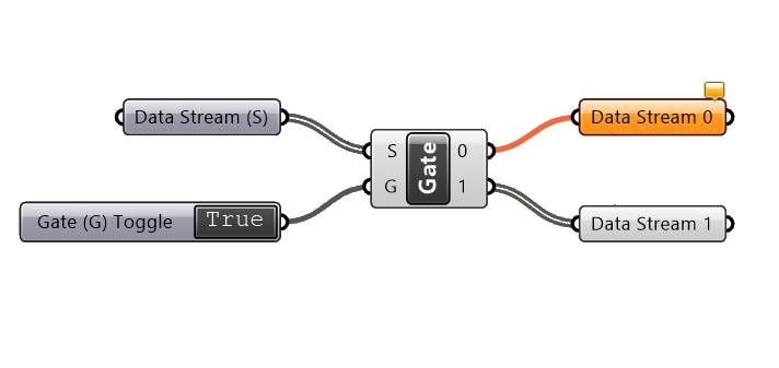
- the Input Stream (S): This is the data stream that will be directed to one of the outputs. Think of it as our train.
- the Gate (G) index: This integer defines which output the Input Stream (S) will be directed to, acting as our railroad switch.
The outputs are simply numbered 0 and 1, they represent the two default ‘tracks’ the data can be guided to. What’s special about these outputs is that only one of them can carry data at any time. If the data is guided to output 0, output 1 is empty, and vice-versa.
Basic Stream Gate Setup with Two Options
By default, the Stream Gate component comes with two outputs: 0 and 1. Here’s how you might set it up:
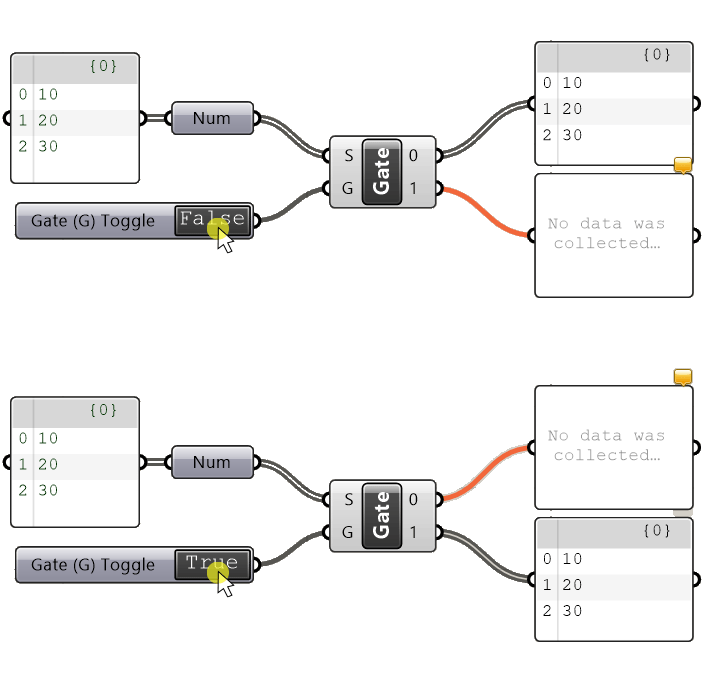
Connect your data stream to the Input Stream (S) and use a Boolean Toggle for the Gate (G) input. Since Boolean Values (True and False) correspond to 0 and 1, this toggle provides a straightforward way to control which output the data stream should be directed to. If the toggle is set to ‘False‘ (0), the input stream will be output to the output 0 and, if set to ‘True‘ (1) it goes to output 1.
In the image above, you can see the inactive output and its subsequent components are orange, indicating no data is flowing through them.
But we are not limited to just two output stream options!
Expanding to Multiple Output Options
To add more output options, zoom in to the Stream Gate component until you see small plus and minus signs. (If this is the first time zooming up close to the component, you’ll see a popup message explaining how you can add or remove outputs.)
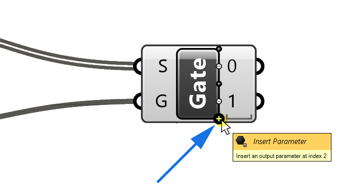
Click on the plus icon to add as many additional stream outputs as needed.
Since there now are more than two output options, we can no longer use the Boolean Toggle to choose the output. Instead, use a Number Slider, with a range matching our output options. For example, if you have four outputs, set the slider range from 0 to 3.
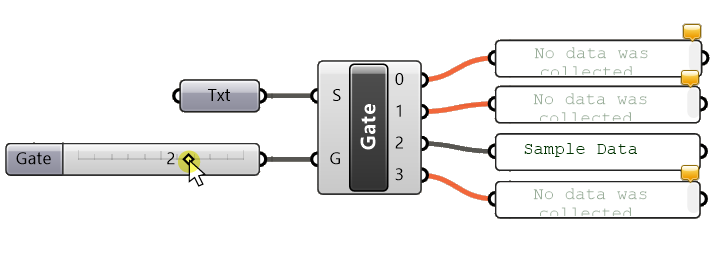
In the example shown above, the Gate input is the number ‘2’, and the Stream (S) input is directed to the ‘2‘ output. All other outputs remain empty.
For detailed instructions on configuring the Number Slider to a specific range, check out my in-depth post about it.
Concluding thoughts
The Stream Gate component is an essential tool for managing data flows in Grasshopper scripts, making it easy to switch between different script paths without manually reconnecting components. With the ability to add multiple outputs, you can efficiently manage complex data streams in your projects.
Happy designing!

