Creating a perforated surface is one of the staple skills of any Grasshopper user. Combining the sculptability of surfaces with patterns and cutting holes into them allows designers to quickly create stunning effects. But creating it is not without challenges. In this guide, I’ll walk you through the process of creating a perforated surface, sharing tips and tricks along the way.
By the end of this article, you’ll be able to confidently model perforated surfaces!
Let’s dive in!
The Basics of Trimming a Surface in Grasshopper
Before we dive in, let’s make sure we cover the core procedure necessary for creating a perforated surface in Grasshopper: trimming a surface. The process of trimming a surface in Grasshopper involves three steps:
- Generating the intersection curve(s) on the surface
- Splitting the surface with the intersection curves(s)
- Removing the surface fragments you don’t need.
The image below shows a simple example of the procedure:
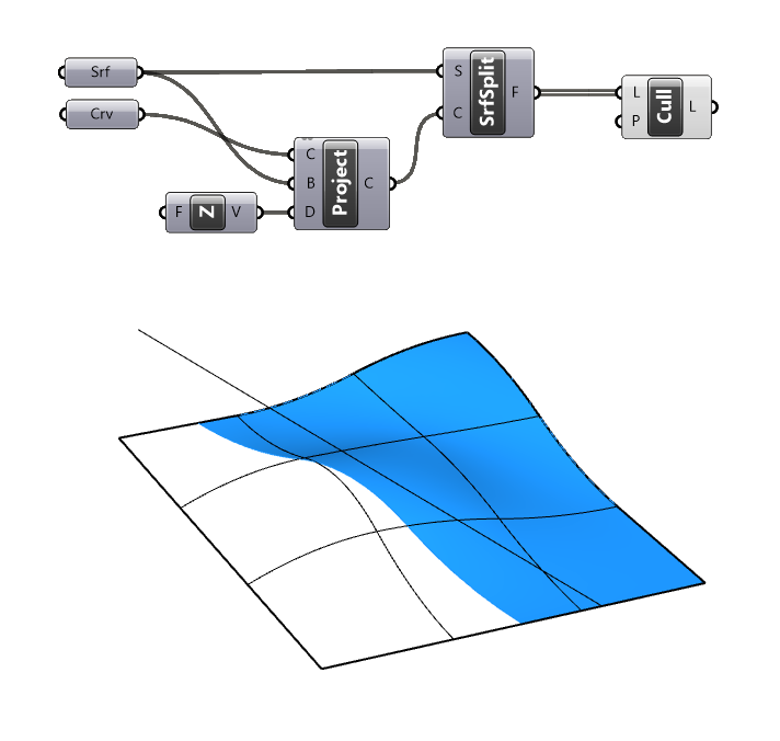
A line is projected vertically onto the surface using the Project component and a Unit-Z vector to create the intersection curve, the surface is split with this intersection curve using the Split Surface (SplitSrf) component, and one segment fragment is removed using the Cull Pattern component.
If you want a more in-depth description of this process, check out the article: How to Trim a Surface in Grasshopper.
Creating a perforated surface is a bit more complex: there are often hundreds of intersection curves and we need a robust way to make the selection of the split surface to keep. With the basics covered, let’s move on to the main tutorial!
Creating a Perforated Surface in Grasshopper – Step-by-Step Tutorial
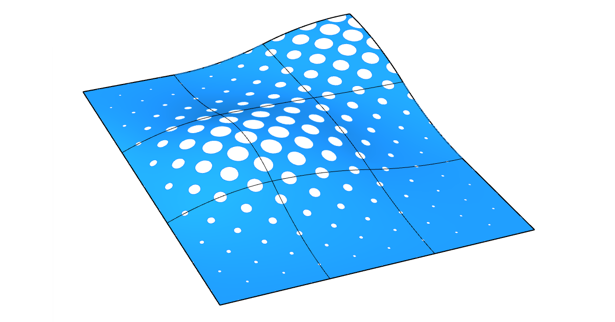
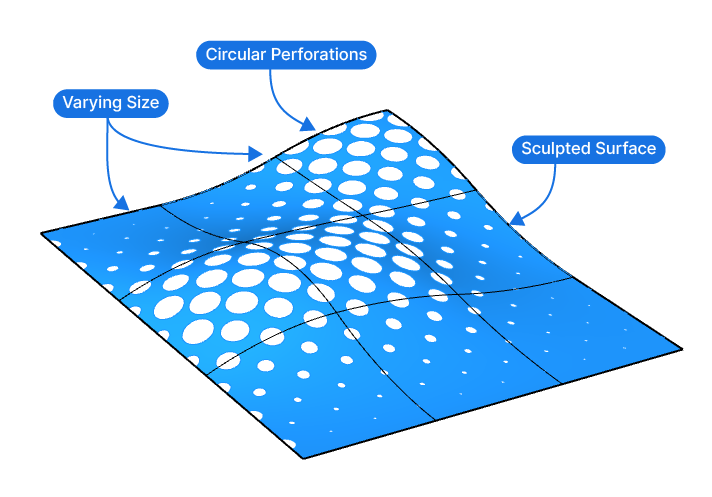
We’ll be creating the following output:
A simple, sculpted surface with circular perforations of varying sizes. The circle size will depend on their height location, creating the following effect:
The tutorial will have two main sections:
First, we’ll create the circle pattern, and then we’ll split the surface and make our selection.
Generating the Circle Pattern
Let’s start by generating the circle pattern that we’ll use to split the surface. In our example, the circles are not in a regular grid, but offset to each other in a checkerboard-like fashion, to create a more interesting effect.
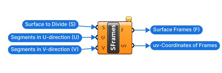
We’ll start by creating a regular grid of points on our surface. To generate the grid, we’ll add the ‘Surface Frames (SFrames)’ component. Add it to the canvas by double-clicking on the canvas and typing “surface frames” into the component search bar, and selecting the first result.
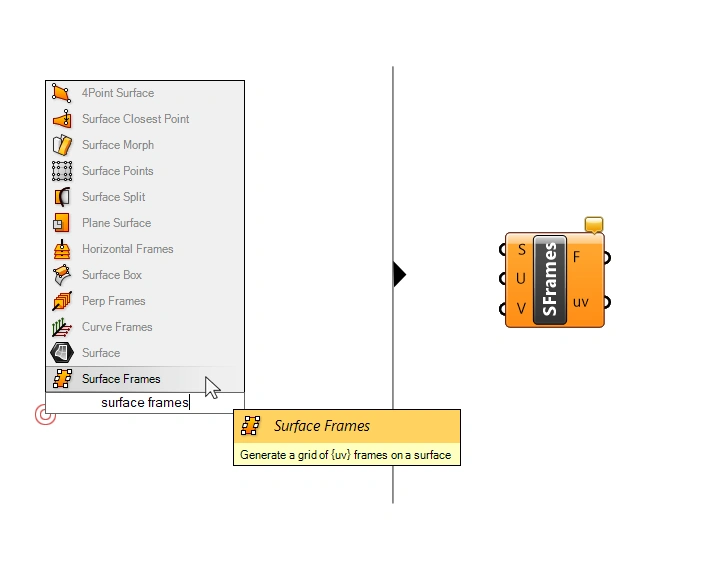
The Surface Frames component has three inputs:
- The Surface (S) to divide (we can go ahead and connect our referenced surface)
- A numerical inputs that allows us to define the Number of Segments in the (U) direction
- A numerical inputs that allows us to define the Number of Segments in the (V) direction
The outputs are the Surface Frames (F) on the surface, which is just a different name for construction planes, and the uv-Coordinates (uv) of the surface at the division points.
Add a Number Slider and connect it to both the U and V Number of Segments inputs. We have a square surface, so that will give us a uniform grid. Give it a value of 18.
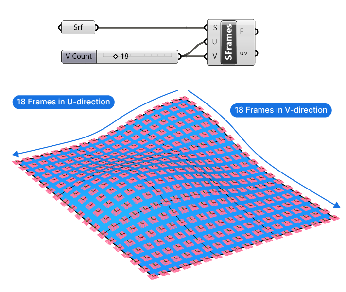
We generated surface frames instead of just points to ensure that the circles follow the surface’s curvature. The planes we generated follow the surface normals and u-and-v directions of the surface and form the perfect base for the circles.
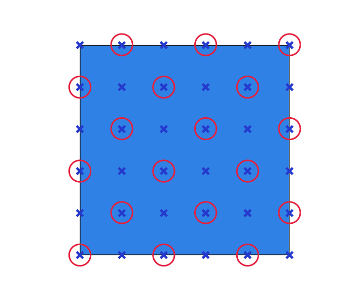
Creating a Checkerboard Pattern
The next step is to create a checkerboard pattern from the grid we generated. A simple way to create it, is to delete every second frame of each row, and shift the deletion pattern every second row, as shown in the diagram below:
To know how to proceed, let’s first study the data structure of the Surface Frames (F) output we have:
By connecting the Param Viewer panel, we see that the surface frames are structured in 19 branches, and that each branch contains 19 items. I’ve visualized the data structure below.
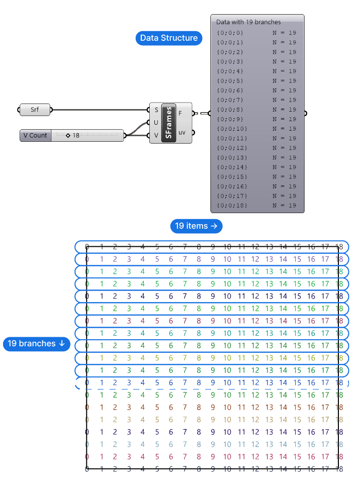
This means that the first step will be to split the branches into two groups, and assign branches to those groups alternatingly. Then, we can create an offset deletion pattern for each group, leading to our desired checkerboard pattern.
Dispatching the Tree Branches into Two Groups
Here’s how we’ll do it: Grasshopper allows us to pick a branch from a data tree by using only its name with the ‘Tree Branch’ component. So we’ll Dispatch the names of the data branches into two lists using a simple True and False pattern. Then, we’ll select every second branch using the Tree Branch component.
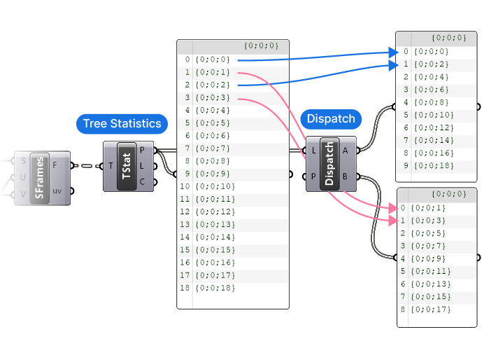
The first step is to extract the names of the data branches, we’ll do so with the Tree Statistic (TStat) component. By connecting any data stream to its single input, this component will return three of its properties: the Data Paths (P) (which are the branch names), the Length (L) of each data branch (the number of items per branch), and the Count (C) (the number of branches in the data tree).
We need the Data Paths (P) output, which collects the branch names in a list, ready to be processed.
To separate the names into two lists, we’ll use the ‘Dispatch’ component. This component takes a List (L) and uses a True/False Pattern (P) to move the items into output A (True) or output B (False). The component comes with a default Pattern (P) input of True, False, which is just what we need in this case.
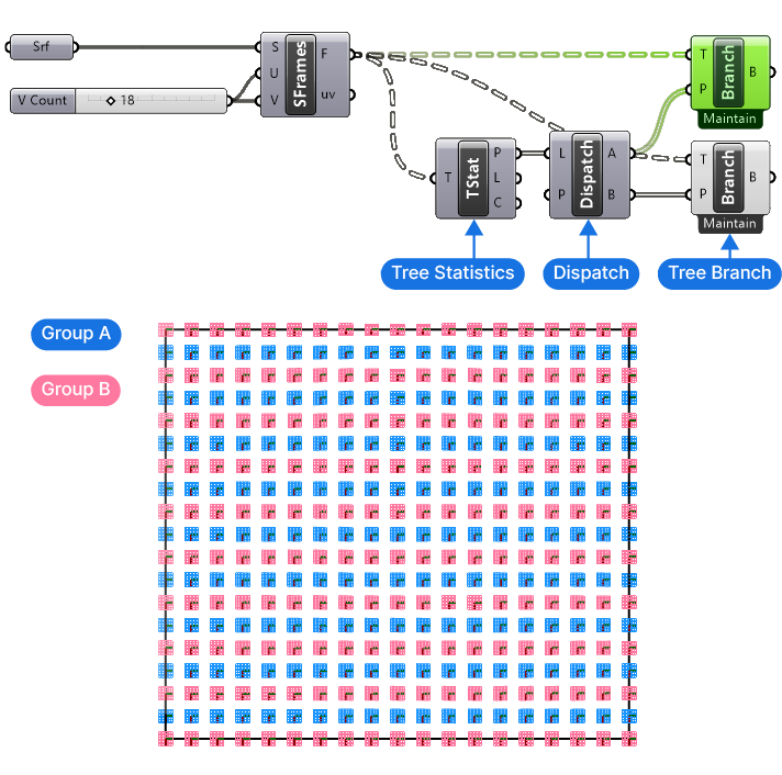
We can now use two Tree Branch components and connect the separate branch name lists to split the Surface Frames (F) rows into two groups. Below I selected one of the Tree Branch components, to show the different groups.
Deleting Every Second Item in Each Branch
Now we can go ahead and delete every second item in the first group and then invert the deletion pattern in the second group.
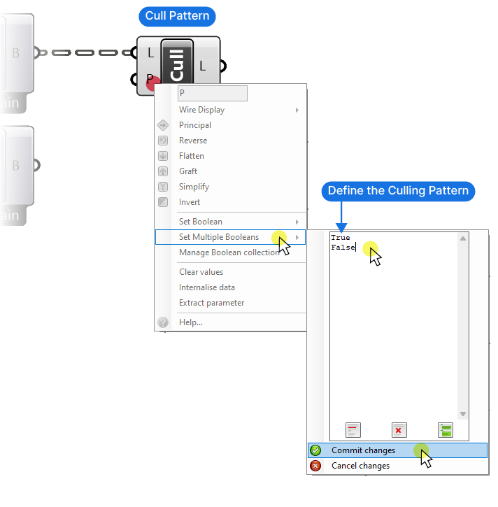
To do so, we’ll use the ‘Cull Pattern’ component. This component will process an input List (L) with a Cull Pattern (P), which is again a list of True or False values. The pattern provides will be repeated as many times as needed to get to the end of the List (L).
We need to change the default Cull Pattern to a simple True and False pattern. To do so, right-click on the Cull Pattern (P) input, go to ‘Set Multiple Booleans’ and type “True” and “False” in two separate lines. Confirm by clicking ‘Commit Changes’.
To create the opposite pattern, we’ll simply copy the Cull Pattern component we just added, connect the second branch, and right-click on the Cull Pattern (P) input, and select ‘Invert’.
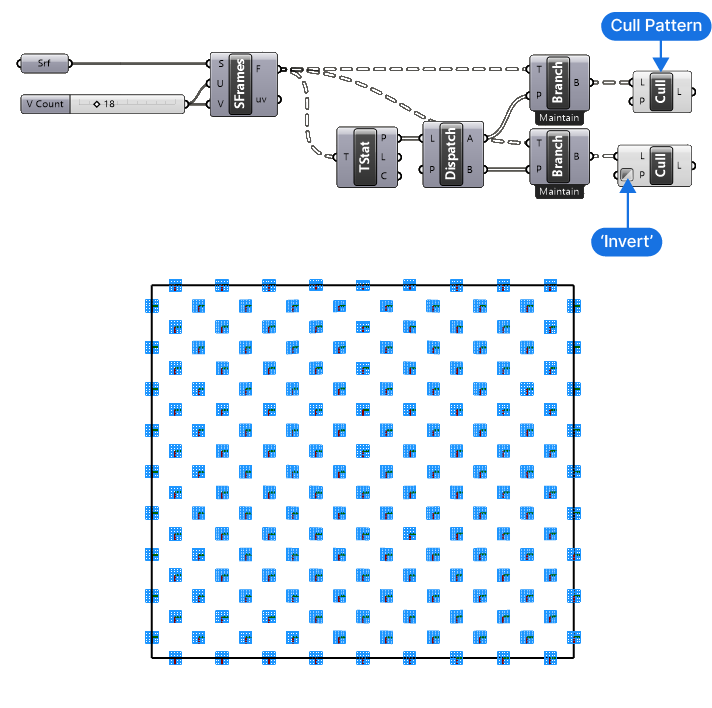
We’ve successfully created the checkerboard pattern! We are one step closer to creating our perforated surface in Grasshopper!
Now let’s create the circles and size them according to their vertical height.
Creating the Circles
Begin by collecting the checkerboard surface frames in a single Data container component. Flatten it by right-clicking and selecting ‘Flatten’. This ensures that we get a single list containing all the items.
To create a relationship between the height location of the circle and its radius, we’ll extract the Z-values of all the frames, and then remap the numbers to a minimum and maximum number we specify.
Let’s add a Deconstruct (pDecon) component. This component will return the X, Y, and Z values as separate outputs. Next we’ll add a Remap Numbers (Remap) component, as well as a Bounds (Bnd) component.
The Z-values are the values we want to remap, so let’s connect them to the Value to Remap (V) input of the Remap component. The Bounds (Bnd) component will return the minimum and maximum values of our Z values, which will use as the Source Domain (S) of the remapping operation.
Finally, let’s add a Construct Domain (Dom) component to define our own minimum and maximum radius numbers with two Number Sliders.
We’ll now create the circles with a Circle component (make sure to pick the one that says: “Create a circle defined by baseplane and radius”). The Plane (P) input is our flattened Data container, and the Remapped Number (R) output of the Remap component contains the Radius (R) for each circle.
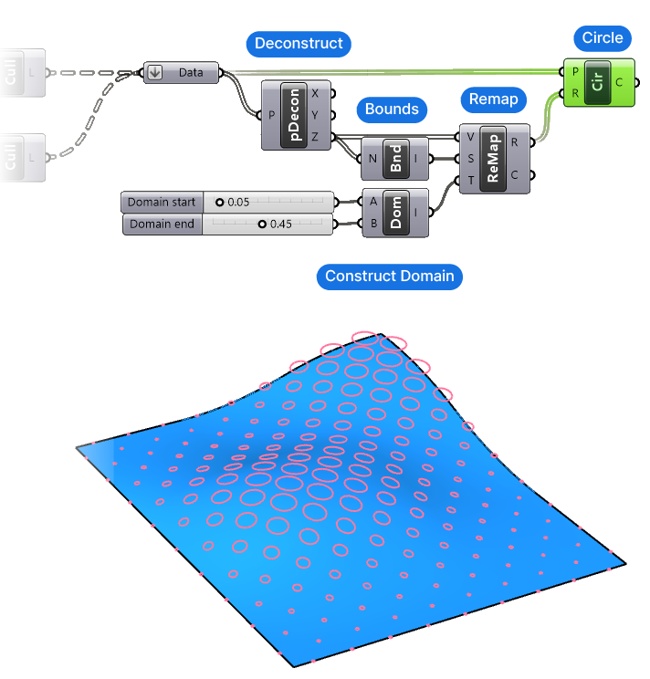
Adjust the minimum and maximum radius size as needed for your particular surface.
Now let’s move on to the most important part: using Grasshopper’s Surface Split component to create the perforated surface!
Splitting the Surface
To split the surface we’ll need our original surface, as well as the circles we’ve just created. I will add a surface and curve data container and connect them to start this new section of the script.
We’ll start with the basic Surface Split component sequence: we’ll add a Surface Split (SrfSplit) component, and connect our base surface. Next we’ll use the Project component (make sure to pick the one that says: “Project a curve onto a brep”), as well as a Z-Unit vector to project the circles vertically onto our base surface.
Make sure to flatten the output of the Project component, as this component will graft the projected curves into separate branches, whereas we need a single list of curves to split the surface with.
Although the circles are already close to the surface, they are generated on a flat plane, meaning that unless we define the projection method, Grasshopper will “pull” the curve onto the surface, which leads to a deformed outline.
Note: I’m using the Z-Unit vector, because my surface is horizontal, use a projection vector that matches your surface!
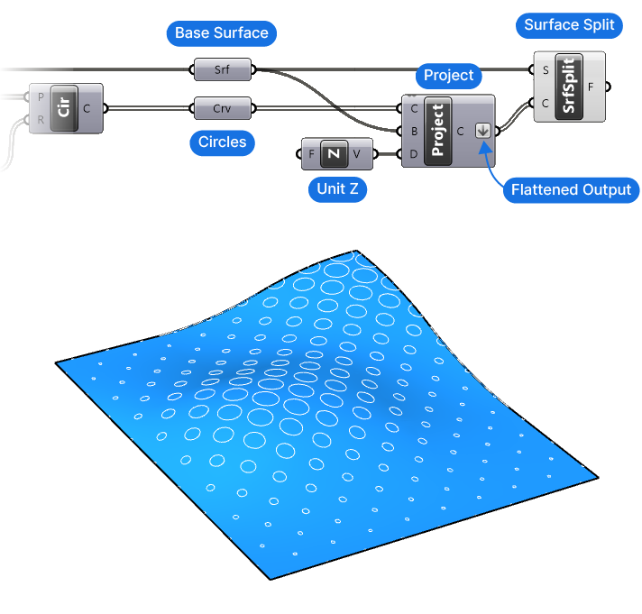
At this point we’ve successfully split the surface, leading to a list of Surface Fragments (F). The last step is to select the right surface!
Selecting the Correct Surface Fragment
Selecting the trimmed base surface is the main challenge when it comes to perforated surface designs in Grasshopper. There are, as with any algorithm, many different ways of making this selection, and ultimately the technique you choose depends on your specific design situation.
I’ve found the following selection method to be the most robust; it works for most use cases without causing unexpected results.
Here is the approach in a nutshell:
The main idea is to generate a point on every surface fragment, and then check whether the point is located inside any one of the curves we’ve used to split the surface. If they are, it means that they are the perforated pieces of the surface. The only remaining surface fragments are the perforated surface.
Now the challenge here is, that the Area component, which usually gives us the centerpoint of a surface doesn’t reliably work in this case, since a non-regularly shaped surface, or one with holes can return a point that’s not located on the surface itself, as shown below:
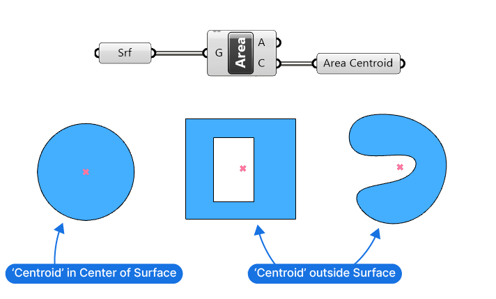
To reliably generate a point on the surface, we’ll use the following method:
Generating Points On the Surface Fragments
We’ll convert the surfaces into meshes, and get one of the triangle midpoints of the resulting mesh. Since meshes made of facets of triangles, and the centerpoint of a triangle, no matter the shape, will always be contained inside the triangle, we get a reliable point we can use as proxy for the surface fragment’s location.
Let’s implement this logic with components!
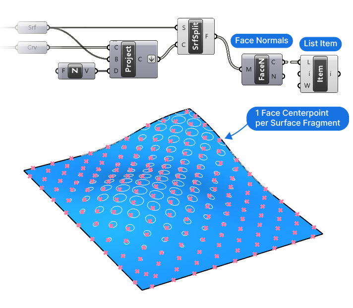
Add a Face Normals (FaceN) component and connect it to the Split Surface output. By providing a surface input instead of a mesh, Grasshopper will automatically convert the surfaces into meshes, and return both the Centerpoints (C) of the faces and the Face Normals (F).
The Centerpoints (C) output contains a list of all the centerpoints of the mesh, and we just need one. Let’s add a List Item component and pick the first item (any item will do, as long as it’s a single one).
We now have a point on each the split surfaces that we can use for the next step: Checking whether the points are inside the circle curves we used to split the surface.
Checking Whether the Points Are Inside the Curves
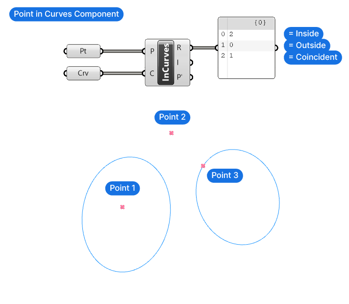
We’ll use the Point in Curves (InCurves) component. Make sure to pick the one with curves (plural), there is also a component that checks whether a point is in a single curve. In our case need to check whether the point is in any of the circles.
The Points for Inclusion (P) input is the points to test, and the Curves (C) are the boundary regions to check against.
The Point in Curves (InCurves) component’s output we need is the first, called Relationship (R). The component will describe the relationship between each point and the curves as one of three numbers:
- 0 means the point is outside the curves
- 1 means the coincident with the curve, in other words on the curve
- 2 means the point is inside of the curves
Let’s connect the circles output to the Curves (C) input, and the output of the List Item component to the Points for Inclusion (P) input. Make sure to flatten the list of points, by right-clicking and selecting ‘Flatten’. The Face Normals component created a new list for every split surface, thereby grafting the data structure, by flattening it, we undo that.
Selecting the Surface With a Cull Pattern
Finally, we can use the Cull Pattern component, connect the output of the Split Surface component to the List (L) input, and the Relationship (R) output of the Point in Curves (InCurves) component to the Cull Pattern (P) input.
While the Cull Pattern (P) input requires a ‘True’ or ‘False’ value to define the Pattern, it will also accept a ‘1’ or ‘0’ to mean the same thing. Our Relationship (R) output is made up of the values 0, 1, and 2, since some points are inside the curves, some so close to the curve to count as coincident with it, and some outside the curve.
Luckily Grasshopper converts any number that isn’t 0 (False) into 1 (which is True). Thanks to this automatic conversion, we get a clear True/False pattern.
At this point the Cull Patterns returns all the split surface parts within the circles, since they are inside the circles and the Relationship (R) output therefore returned ‘True’. To select the perforated surface instead, simply invert the Cull Pattern (P) by right-clicking on the input and selecting ‘Invert’.
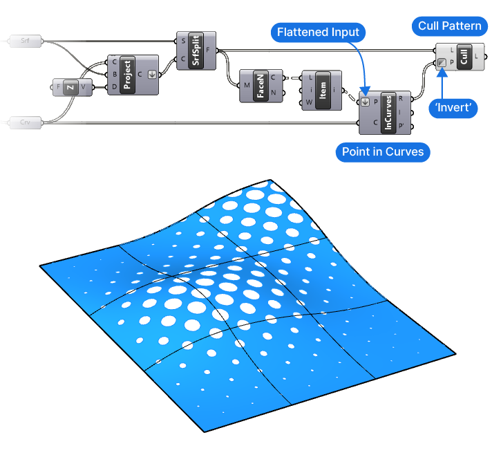
There we have it! We’ve successfully created a perforated surface in Grasshopper!
Perforated Surface in Grasshopper – Final thoughts
Creating a perforated surface in Grasshopper is an essential skill for architects and designers, and with this guide, you should have a clearer understanding of the process. Use the approach outlined in this article as a starting point and tune it to your specific needs!
If you’ve found this guide helpful, check out Grasshopper Pro. It’s our comprehensive online course for architects is designed to help you fast-track your learnings using a structured and comprehensive approach. It’s truly the only course you’ll ever need to become a Grasshopper pro! Dive in and elevate your design skills to the next level.
Happy designing!