Creating a surface from points in Grasshopper is a common task for terrain modeling, topography, or reconstructing geometry from measured data. In this tutorial, we’ll cover three practical methods: using the Surface from Points component, the Patch component, and a Delaunay triangulation to generate a mesh. Each method has different strengths depending on your point data and precision needs, and we’ll walk through when and how to use each.
Methods for Creating a Surface From Points in Grasshopper
The best method depends on your point data and the accuracy you need. Consider:
- Are the points random, evenly spaced, or extracted from an existing surface?
- Do you need an exact fit, or is an approximation acceptable?
- Will the output be a NURBS surface or a mesh?
Here are three approaches you can use:
- Patch Surface – Fast and flexible, ideal for approximations.
- Surface from Points – Creates accurate NURBS surfaces when points are structured in a grid.
- Delaunay Triangulation – Generates precise meshes from unordered points, great for large datasets.
In the sections below, we’ll look at how each method works and when to use it.
Finally we’ll cover how we can leverage the techniques above to turn contours to a surface in Grasshopper.
Creating a surface from points with the ‘Patch’ component
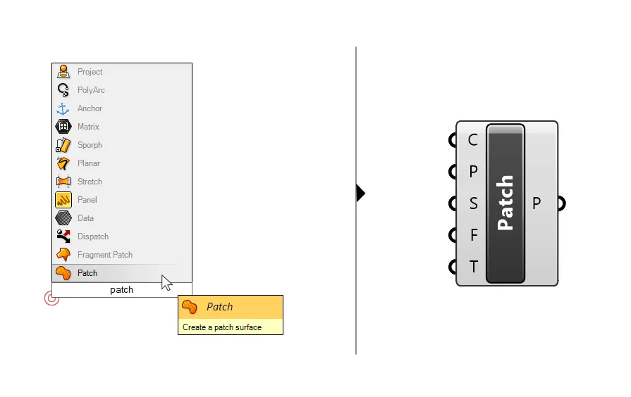
One of the fastest ways of creating a surface from points is to use the ‘Patch’ component. Add it to your script by double-clicking onto the empty Grasshopper canvas and typing ‘Patch‘.
Much like its Rhino counterpart, this component will generate a surface that will try to fit through all input points provided.
Let’s take a closer look at the inputs and outputs. The component allows two different kinds of inputs: points (P) as well as curves (C).
We can provide just points, just curves, but also a mix of both! The component will try its best to create a surface that goes through all the input geometry. The component also accepts a mix of open and closed curves.
How to control the precision of the patch surface
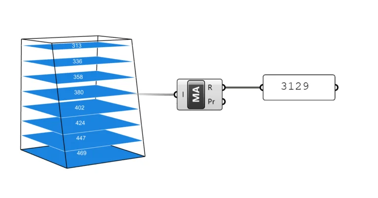
We can use the third input, Spans (S), to define the resolution of the patch surface. The number we provide will define the number of U and V control point curves of the surface. The higher the number, the more accurate the fitting will be, but be careful when increasing the default value of 20, as the computation time will rapidly increase with every added span.
Here you can see how the spans affect the precision of the surface fitting through the points:
With fewer span, the maximum deviation between any point and the surface is quite high. As the span number increases, the maximum deviation diminishes, but the surface becomes more complex and computationally more demanding.
Adjusting the Patch Flexibility
The following input, the Patch flexibility (F) takes a number between 0.00 and 1.00 and it can be used in addition to the spans to control how strict the surface fitting should be. A more flexible surface will adapt and bend more easily to match the input points more closely, at the cost of potentially creating unnatural bends in the surface.
A flexibility value of 0.00 means that the surface will be very smooth and simple, at the cost of more distance between the input points and the surface. See below how it affects the resulting surface:
The last input controls how the Patch component creates with the border of the resulting surface. To fit through the input geometry, the surface needs to extend beyond it – Grasshopper will determine how far the border should reach. We can’t really control where exactly the border will be when using the Patch component.
You can expect the outline to always be rectangular. The patch component will start the fitting process by generating a bounding rectangle around the geometry to be patched and use that as a guide for the extents of the surface. After accounting for the fitting deformation, the outline is usually a slightly deformed rectangle.
Limitations
As these options show, the Patch component will not return a surface that perfectly fits through all the points, it create an approximate surface fitting. To get the best results, make sure to provide a clean collection of points for example by avoiding big jumps in height between two close points.
If you want to have more control over the border of the surface and make sure that the surface runs exactly through the points you provide, you can use the Surface from Points component we’ll discuss next.
Creating a Surface From Points in Grasshopper with the ‘Surface From Points’ Component
If you are trying to create a surface from points in Grasshopper, chances are you found the ‘Surface from Points‘ component in the component search bar, but it didn’t exactly do what it promised. For the ‘Surface from Points’ component to work, we need to prepare the set of input points in a very specific way. Read on to learn how:
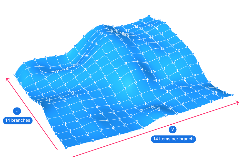
This easiest way to think of the Surface from Points component is to think of a normal surface in Rhino. Imagine turning on the control points of that surface. All the surface control points will appear, neatly ordered in a two-dimensional grid. They will describe a grid for two sets of curves: the U and the V curves that make up the surface.
In the example below, the surface has 14 branches containing 14 control points each.
The ‘Surface from Points’ component in Grasshopper needs exactly the same kind of point organization to create a surface – instead of having the surface and visualizing the control points, this component will do the reverse: if we provide all the control points, it will create a surface from them.
Let’s take a close look at the component. You can add it to your script by double-clicking onto the empty canvas and typing ‘Surface from Points’ into the search bar.
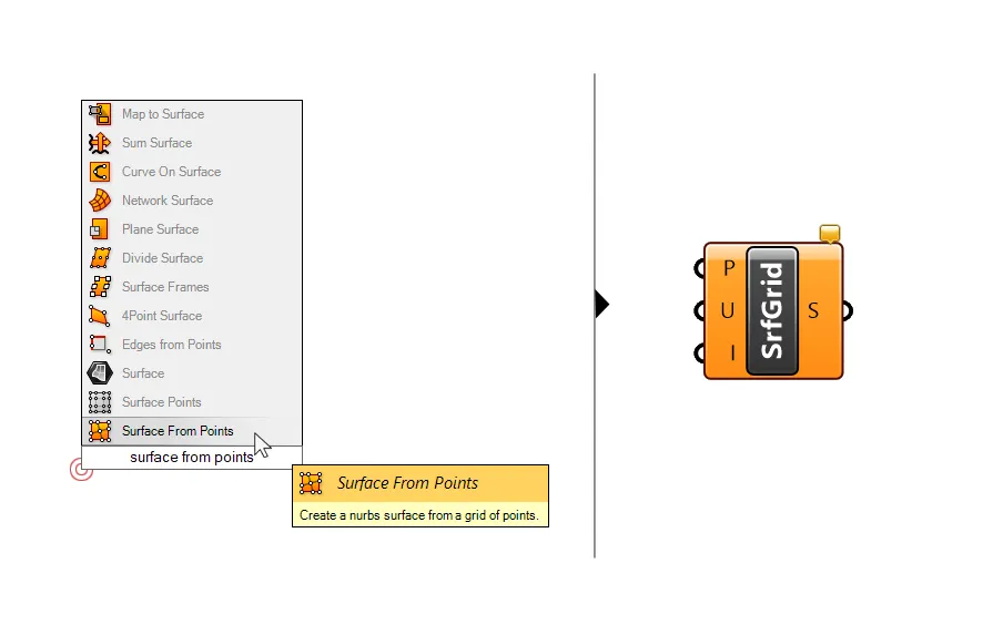
The component has two simple inputs: the set of points (P) to create a surface from, an input (U) that specifies the number of points in the {u} direction (more on that in a second) and a Boolean toggle (I) for turning interpolation on and off.
How to prepare the input points
For the surface from points component to work we need to ensure the input points follow these rules:
- All the points are in a single list
We don’t need to have any particular kind of tree structure, that for example, organizes the points into branches along the U or V direction. The component just needs a list containing all the points needed for the operation. - We must provide an even number of points
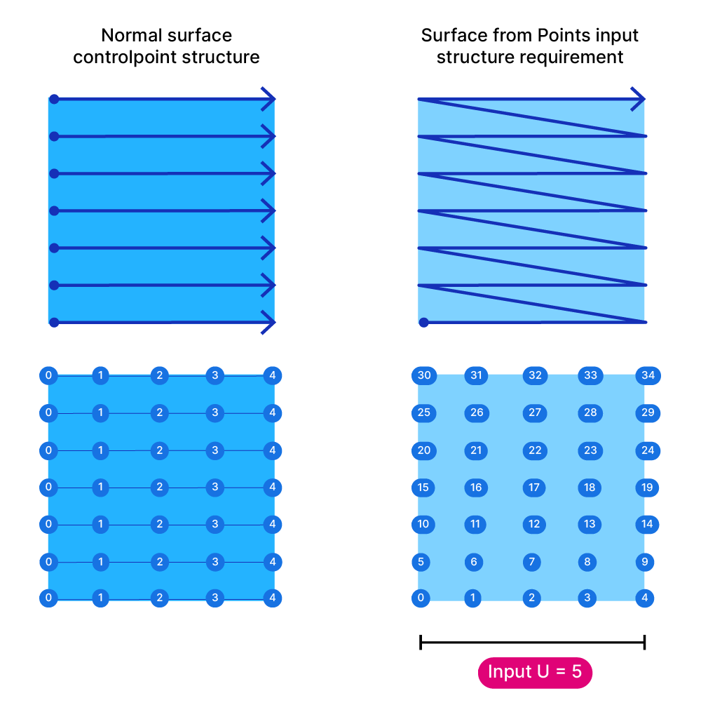
Since the component will try to create a UV structure from the input points, we need to make sure the number of points allows for such a structure. If we miss a single point, the component will fail! - Although the points don’t need to be structured in branches according to the U and V directions, they need to be in the correct order. Imagine a tree structure that contains all the points ordered in the U direction in branches. If you were to flatten that data structure – that’s the point order the input needs to look like.
In addition to setting up the points this way, we need to provide the number of elements in the {u} direction. Since the points are ordered, but they are all in the same list, in order to create a surface, Grasshopper needs to re-create the structure, but it needs some help.
We need to tell it the number of points in the {u} direction. With this information, it will partition the flattened list of points and create a branch for each row of points in the U direction. At that point the component can finally create a surface from the points.
Common application
As you can see there are quite a few requirements for the input. Using this component makes most sense when we are extracting the control points of a surface, modifying them, for example with vectors, to then recreate a surface from them.
In that case all the point preparation conditions are met: all points will be in a list, we are going to have an even number points since all surfaces have an even number of control points, and we can be sure that the points are in the correct order.
Creating a Surface From Points in Grasshopper with a Delaunay Triangulation
If we are dealing with a large number or unordered points, neither the Patch component nor the Surface from Points component will be effective. The Patch component will reach its limits, as the bigger and more precise the surface gets, the heavier it will become.
And the Surface from Points component won’t be able to deal with the unsorted list of points.
To create a surface from height points we can create a mesh that triangulates all the points we provide.
This technique has three main advantages:
- The Delaunay Mesh component is extremely fast, it can process thousands of points easily.
- The output is a very light mesh, much lighter than a complex surface would be.
- The resulting mesh will precisely run through each point in the collection.
How to use the Delaunay Mesh component
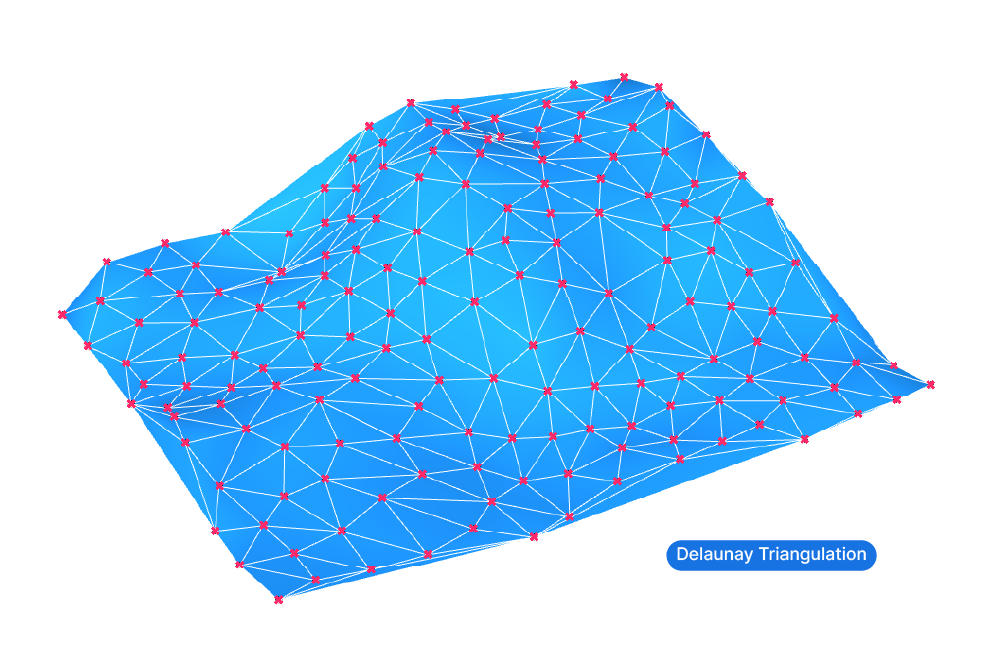
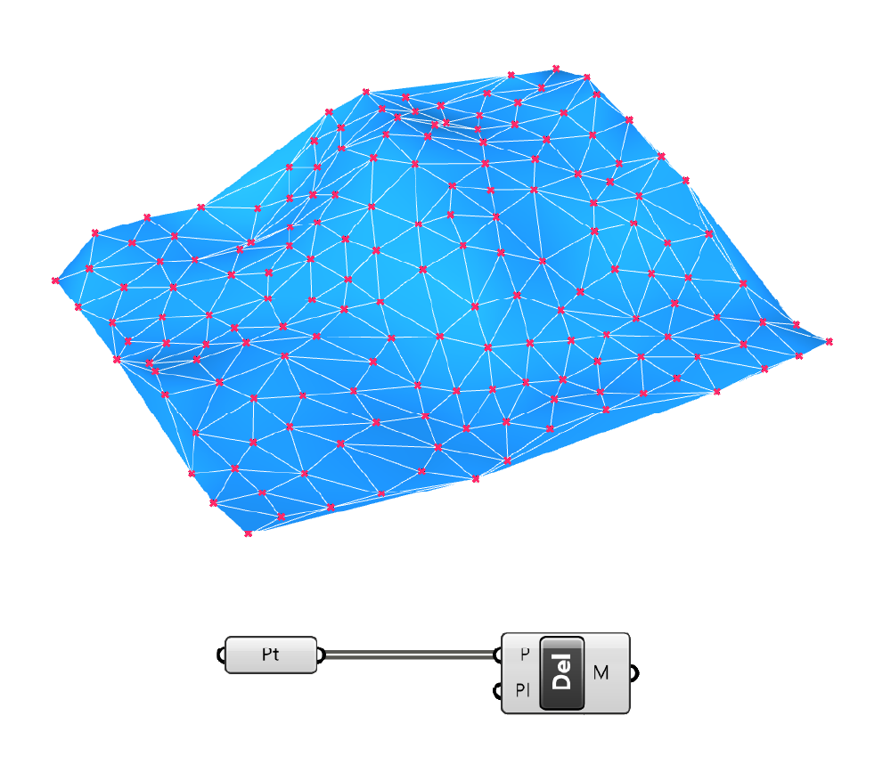
To create a triangulated mesh from points, we are going to need a component called ‘Delaunay Mesh‘. Add it to the canvas by double-clicking and typing its name into the component search bar.

The component is very straightforward: all we need to do is provide a list of points as input. The points can be in a completely random order. The component will use an algorithm to determine adjacent points and connect three points each with a mesh triangle – the result is a continuous, triangulated mesh.
Depending on the size of the resulting mesh and your needs, you can turn the mesh into a polysurface by baking the mesh (select the mesh component and hit ‘insert’ on your keyboard) and running the Convert to NURBS command in the main toolbar.
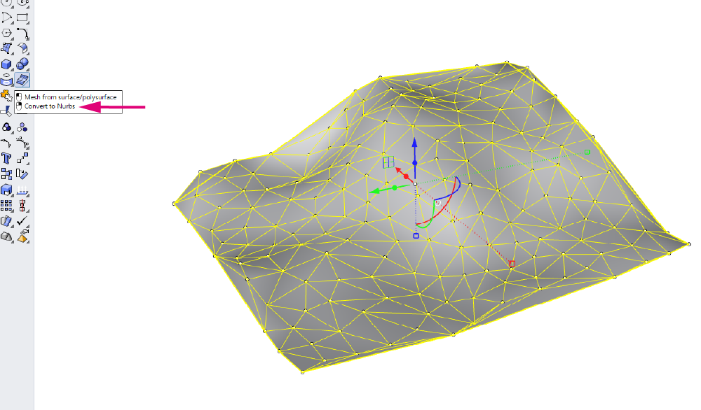
You will get a polysurface or Brep that you can extrude to create a solid. That way you can use it for Boolean Operations.
Cleaning up a triangulated mesh
The Delaunay mesh will triangulate the points – the cleaner our point input is, the cleaner the resulting mesh will be.
By providing a relatively uniform point spacing, the triangles will have a more uniform size, resulting in a cleaner mesh.
While the Delaunay algorithm works well for points that are surrounded by other points, the perimeters of the resulting mesh will usually be less clean. As the points become less frequent towards the perimeter of the height point collection, the triangles will become more and more distorted.
Since we don’t usually need a terrain at these outermost areas, the simplest way to get to a cleaner terrain mesh is to simply trim the mesh and only keep a certain part of the mesh.
We can simply draw a rectangle in the top view, extrude the rectangle to a height where it intersects with the mesh, and then run the MeshSplit command in Rhino. Finally select and delete the unclean parts of the mesh.
How to turn contours to a surface in Grasshopper
In architectural practice we are often faced with the problem that site files are provided as DWG files with height points or contour lines, but without a surface connecting them. To model the topography of the site, we can turn the contours to a surface with the help of Grasshopper.
To create a closed surface from height points or contour lines in Grasshopper, we can use two techniques, depending on the size and precision requirements of the site model.
- If the site is small and the contour lines describe a relatively even terrain with a slight slope, we can use the Patch component. Reference all the height points or contour lines to respective container components in Grasshopper and connect them to the appropriate curve and point inputs.
Make adjustments to the resulting surface with the remaining inputs, if necessary.
- If the topography has a lot going on or if the area to cover is quite large, the Patch component’s output will either become too heavy or too imprecise.
In that case creating a triangulated mesh is a better option.
How to create a triangulated mesh from height points
To create a triangulated mesh from heightpoints, reference them to a point container in Grasshopper and then plug them into a Delaunay Mesh component.
The component will create a mesh made entirely of planar triangles that connect all the input points you provided. You can then bake the mesh and turn it into a polysurface if necessary.
How to create a triangulated mesh from contour lines
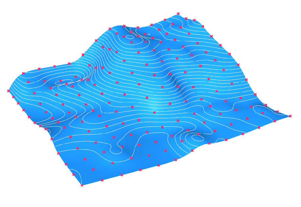
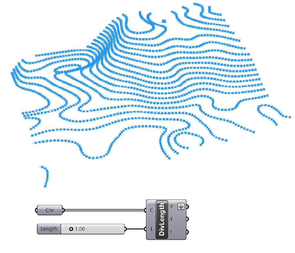
If your starting point is a set of contour polylines, you can still triangulate the mesh but first you need to extract points from the contour lines.
Use a Divide Length component to generate points at regular intervals along the contour lines. Pick a distance that meets the precision needs for your model. For height lines of 1m for example, a division length of 1m will create a relatively uniform mesh.
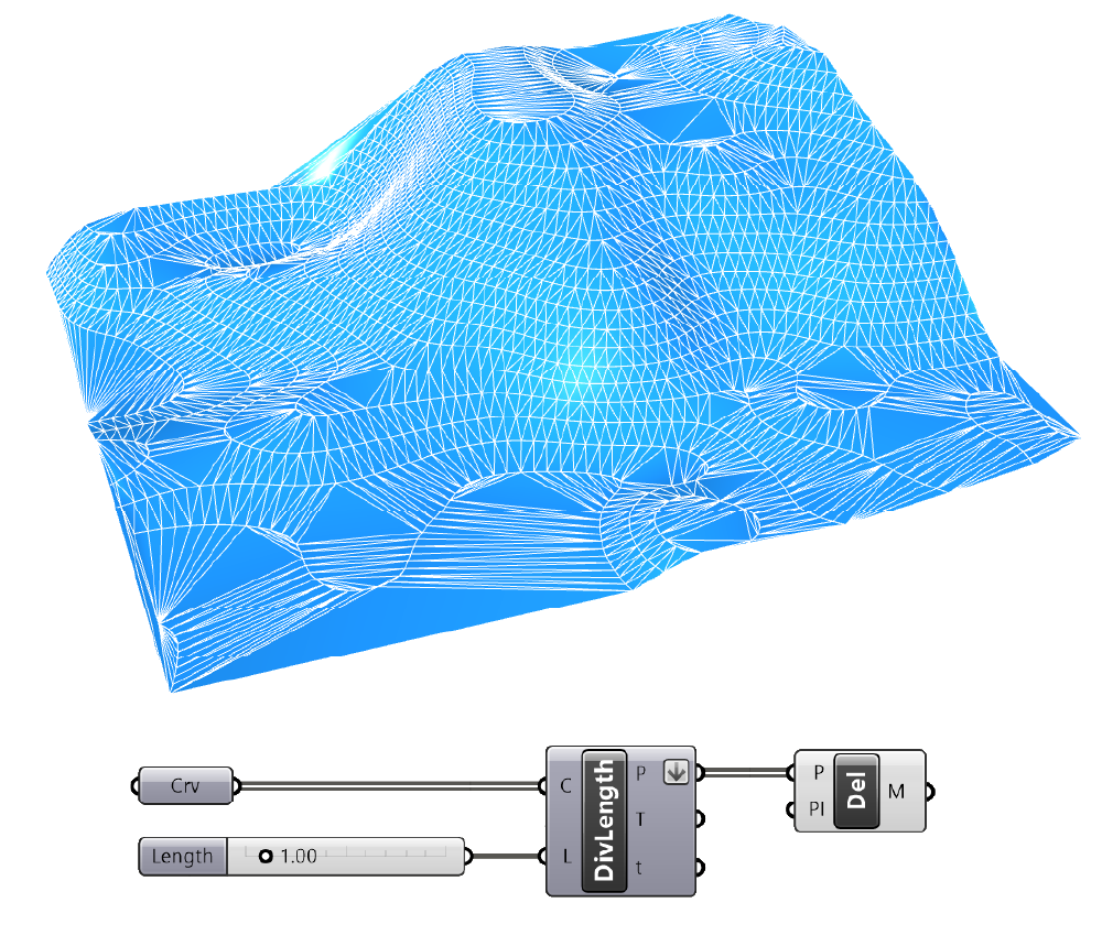
Then use the ‘Delaunay Mesh‘ component to generate the mesh from the points.
As you can see below, areas with a lower sample point density like planar areas of the terrain are not covered in as much detail as the rest. This becomes most evident towards the edges.
When it comes to turning contours into a surface in Grasshopper, consider what you want to use the resulting topography for. Will it be part of the design and will you need to modify it? Then creating a single surface with a Patch component might be the most useful option. Will it just be used to create a context model and won’t need to be touched after creating it? In that case a triangulated mesh will keep your Rhino file light.
Concluding thoughts
In conclusion, you can create a surface from a set of points in a variety of ways in Grasshopper. The ‘Surface from Points’ component, the ‘Patch’ component, and creating a Delaunay triangulation that results in a mesh are all great options that offer different advantages and drawbacks.
While the ‘Patch’ component is one of the fastest ways to create a surface, it may not provide the most accurate results and does not allow for much control over the border of the surface. On the other hand, the ‘Surface from Points’ component offers more control over the surface, but it only has a very specific use case. Lastly, creating a mesh with a Delaunay triangulation provides a more detailed and accurate surface, but requires a greater level of expertise to work with. Regardless of the method you choose, it is important to make sure that your input points are clean and well-organized to get the best results.
If you are new to Grasshopper and you would like to fast-track your way to Grasshopper mastery, check out our online course: Grasshopper Pro – Grasshopper for professional architectural practice.
See you next time!