Looking to breathe life into your designs by creating dynamic shapes that respond to the twists and turns of a curve? Knowing how to extrude elements perpendicular to a curve in Grasshopper is key. In this tutorial, I will unravel the magic behind generating perpendicular vectors to a curve, diving deep into curve tangents and the rotate component. Plus, I’ll guide you on harnessing the power of the Amplitude component to dictate the extrusion length. Whether you’re just starting out or you’re a seasoned pro, this guide has you covered.
Let’s dive in!
How to generate perpendicular extrusion vectors
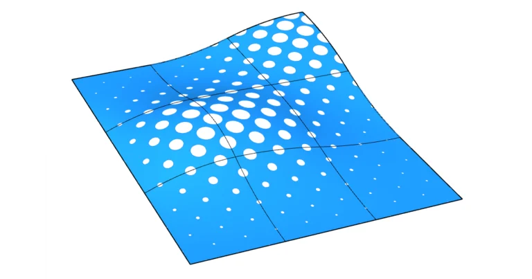
Whenever we are working with a dynamic, curvilinear design and we want to detail it by populating it with elements like louvers, we are faced with the problem that each element needs to be extruded in a different direction, perpendicular to the base curve.
Let’s start with the basics: We need two elements to create extrusions in Grasshopper: the objects to extrude (curves or surfaces) and the extrusion vectors.
There are several ways of manually creating vectors in Grasshopper but in this case we want to generate the vectors based on our existing base curve. We want to use the curvature of the base curve at the location of each louver to inform the louvers’ extrusion direction. Using this approach we can generate as many extrusion vectors as our (ever-changing) design requires.
The core process to generate individual, perpendicular vectors for each louver along the base curve is to:
- find the tangent vector of the curve at that point
- then rotate the tangent vector by 90 degrees, to generate a vector that is exactly perpendicular to the curve at that point
- and finally control the extrusion distance with the Amplitude component.
The first step is to find the tangent vectors. The easiest way to get them is to use curve division components that automatically output the tangent vectors.
Here is each step in detail:
Using curve division components to extract tangent vectors
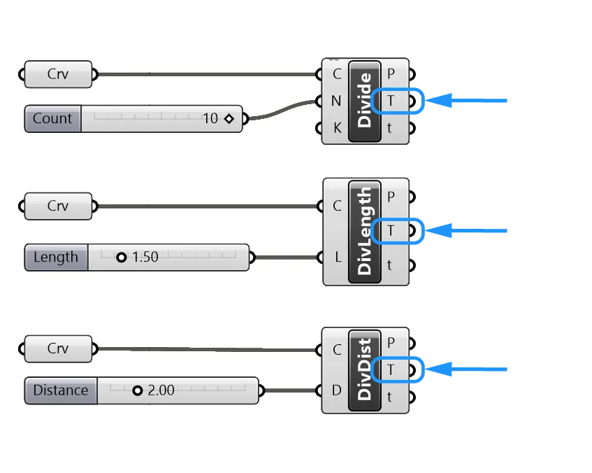
Curve division components allow us to easily generate division points on a curve. We can subdivide a curve in different ways, for example by specifying a number of divisions, a division length or a division distance.
You can find these three curve division components by double-clicking on the empty canvas and typing their names into the search bar: Divide Curve, Divide Length, Divide Distance.
Using these curve subdivision components is the easiest way to quickly generate points on a curve. An added benefit of these components is that they not only generate the points, they also provide us with curve properties at those division points.
Among them: the tangent (T).
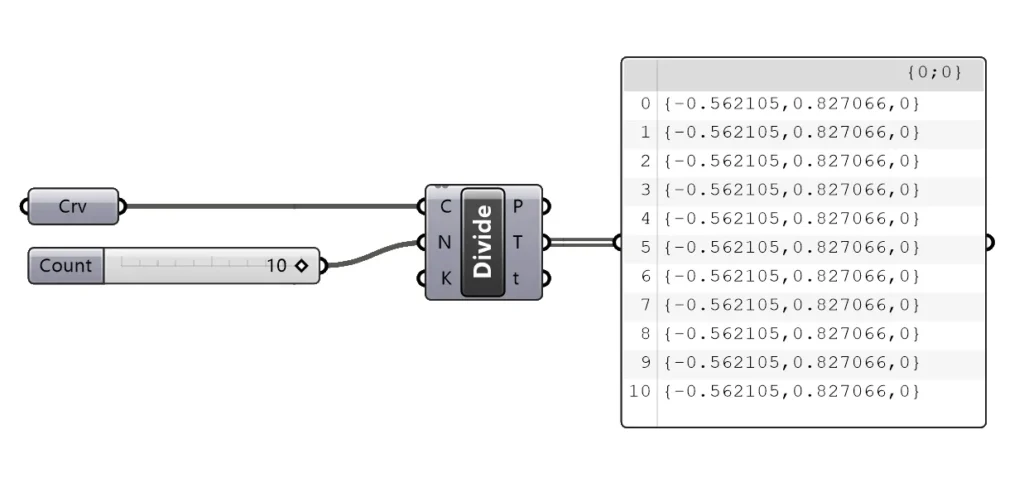
If we look at the contents of the tangent output in a panel, we see that it is a simply vector defined by three coordinates, X, Y, and Z values in relation to the origin {0,0,0}.
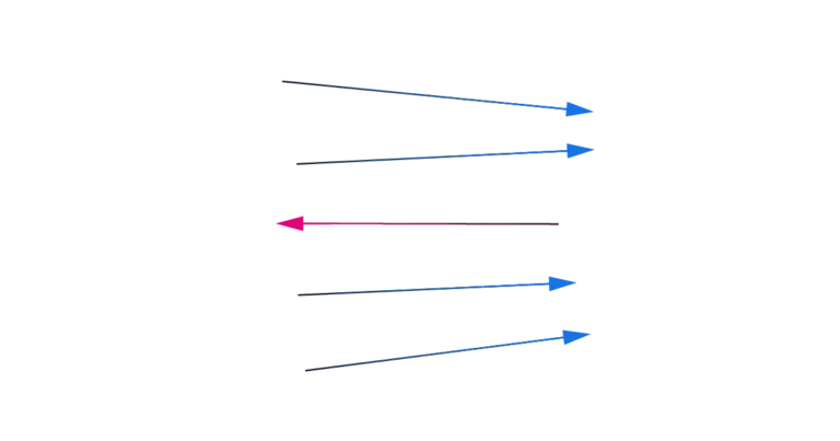
Rotating the tangents to create perpendicular vectors
To create our perpendicular vector, all we need to do is rotate this vector by 90 degrees. This will create a vector that is normal to the curve at the division points.
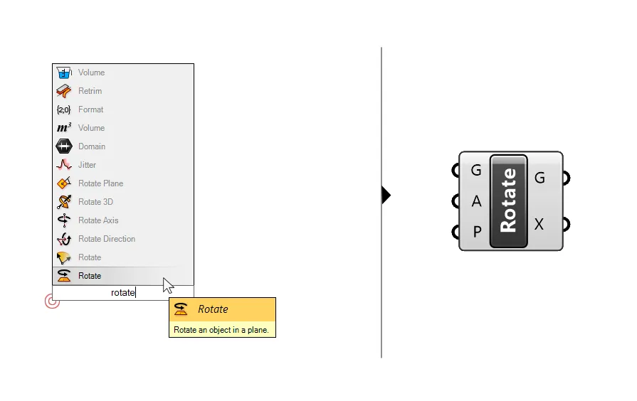
To rotate the vector we use a simply Rotate component. Type ‘Rotate’ into the search bar to add it, make sure to pick the one that says ‘Rotate an object in a plane’, as many rotate components will come up.
All that’s left to do is connect the tangent T output to the first input of the rotate component that says ‘Geometry to rotate’ (G).
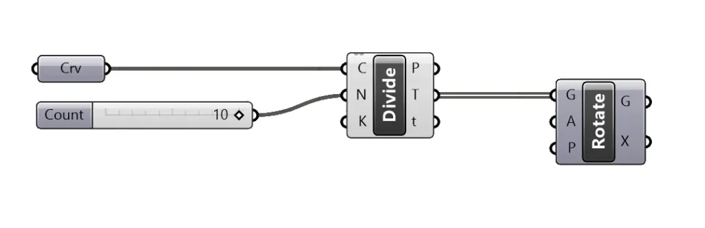
With the following two inputs of the rotate component we can change the rotation angle and the rotation plane.
Both these additional inputs come with a default value. The default rotation is 90 degrees (although it is expressed in radians: pi*0.5). And the default rotation plane is the world XY Plane, or the ground plane in Rhino. In most cases that’s the plane we need.
If we rotate normal geometry like curves and surfaces, we would need to specify the rotation plane since its the point the geometry is rotated around, but since the start point of all vectors is always the origin point {0,0,0}, the default value is already correct.
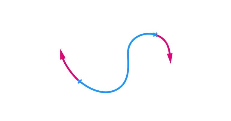
Visualizing the vectors
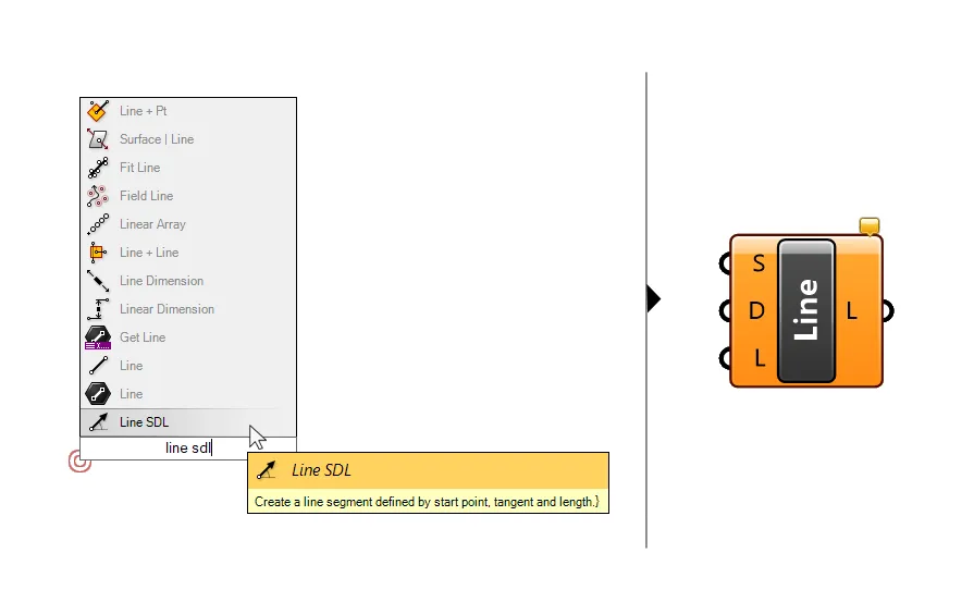
Sometimes it’s helpful to visualize the vectors we just created, to make sure they are pointing in the right direction. A simple way to do that is to draw a line with a component called Line SDL.
SDL stands for start, direction and length. As the name suggests the component creates a line based on these three properties.
Type “Line SDL” into the search bar to add it to the canvas.
To use it to visualize the perpendicular extrusion vectors, we can use the division points as the start point of the curves, and our rotated tangent vectors as the direction. We can leave the length at its default value of 1.
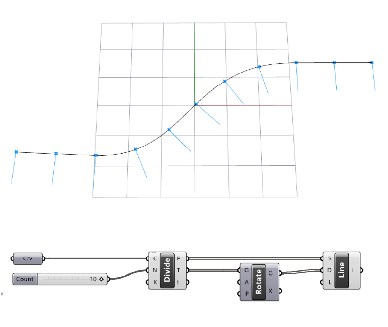
Use this component to make sure the vectors are where you want them to be to avoid surprises later on.
You can also use these curves to develop the actual louver geometry!
Defining the length of the perpendicular extrusion
At this stage we can use these rotated tangent vectors to extrude any geometry perpendicular to the curve. For this example I created vertical lines at each division point with the Line SDL component and a Unit Z vector as geometry to extrude.
The perpendicular vector we generated has a default length of 1, since the original tangent vector has that default length.
Use the Amplitude component to control the extrusion length and finally extrude the curve or surface perpendicular to the curve.
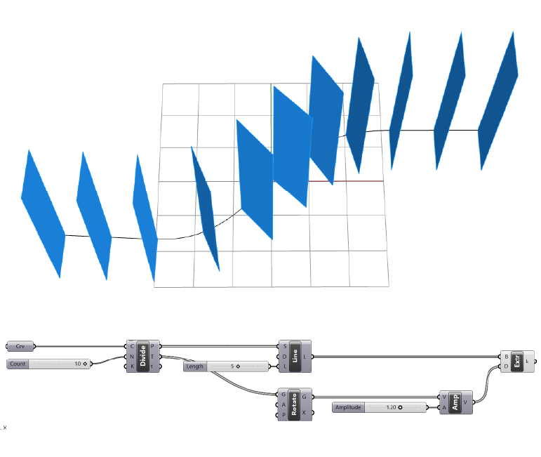
Tip: Keep in mind that depending on the direction of the curve, the perpendicular vectors can face in one direction or the opposite direction. You can solve this by either flipping the direction of your curve, or by specifying a negative negative value as the factor input of the Amplitude component.
How to extrude perpendicular to a surface
Since curves are 2-dimensional elements, using their tangents to define a perpendicular extrusion direction works well when the curve is planar and following one of the main Rhino construction planes, but what if we want to extrude surfaces that are rotated freely in space?
In that case we can use a similar process, we’ll extract the geometric properties of the surface at a specific point and use that information to generate a vector that is perpendicular to the surface.
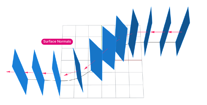
Let’s continue with our example: We have generated vertical surfaces, but we now want to add some thickness to our louver geometry. This time, instead of a tangent vector, we’ll extract the surface normal from each louver surface, and use it to extrude the louver perpendicular to the base surface.
Using the Evaluate Surface component to get the Surface Normal
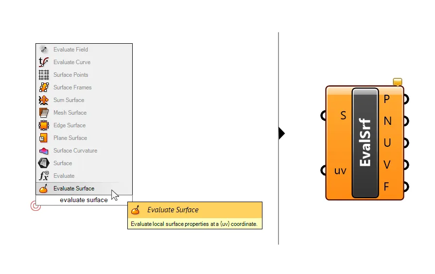
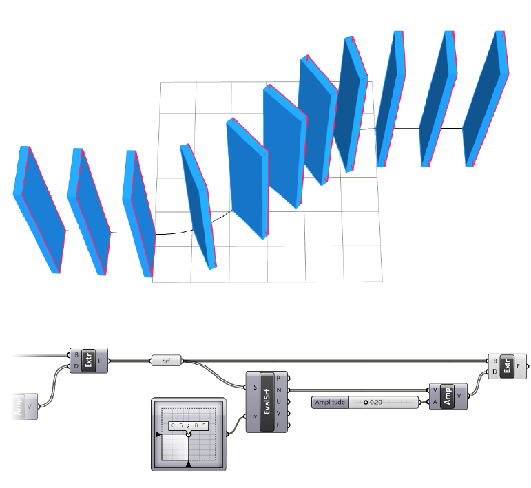
To extract the surface normal we’ll use a component called Evaluate Surface. Add it to the canvas by typing ‘Evaluate Surface’ in the component search bar.
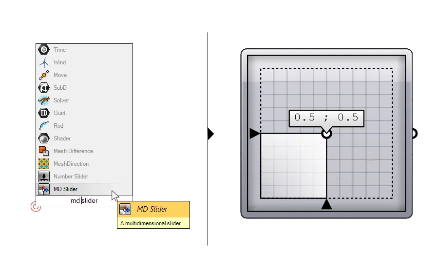
The component has two inputs: the first is the surface to evaluate, and the second the 2-dimensional evaluation parameter that describes a point on the surface. To evaluate the base surface at its center point, we can use the 2-dimensional evaluation parameter {0.5, 0.5). This will return a point located in the middle of the surfaces’ U and V directions.
The easiest way is to add a component called ‘MD Slider’. MD stands for multi-dimensional: it allows us to define a 2-dimensional parameter by sliding the button in the middle, much like a 1-dimensional Number Slider. Leave it at the default to get an evaluation value of 0.5 and 0.5.
Make sure to right-click on the surface input and select ‘Reparametrize’ to reset both surfaces domains to a range from 0 to 1.
The Evaluate Surface component outputs a number of different surface properties – the one we are looking for is the surface normal, the second output (N).
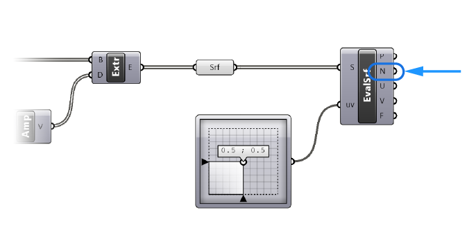
The surface normal already describes the vector perpendicular to the surface at the evaluation point we specified (in our case the center point), so we don’t need to rotate it.
Defining the depth of the perpendicular extrusion
The only thing left to do is to control the thickness of the perpendicular extrusion along the surface. We’ll do that with the Amplitude component. The surface normal is going to be our extrusion direction, and a second number we provide will determine the extrusion length. The result will be a closed polysurface or Brep.
Conclusion
By following the steps outlined in this tutorial, you can easily extrude a curve or surface perpendicular to a curve in Grasshopper. By understanding how to generate a vector that is perpendicular to a curve at a specific point and how to use the Amplitude component to define the extrusion length, you can take your Grasshopper modeling skills to the next level and create a wide range of complex shapes and forms.
We hope you had as much fun reading this tutorial as we did writing it. With this new skill under your belt, the sky’s the limit for your Grasshopper creations. Go out there and make something awesome!