What is an Image Sampler?
Imagine you’ve got an image with a pattern or gradients that you think would make an awesome basis for a design. The Image Sampler component in Grasshopper is your go-to tool for making that happen. It lets you pick up color or brightness values from any image and use those to control your design parameters.
Whether you’re designing an intricate façade or the topography of a landscape, the Image Sampler seamlessly connects the visual inspiration of your chosen image with the parametric details in your project. It makes creating complex patterns both more intuitive and visually driven.
In this post, I’ll give you a complete overview of the Image Sampler component in Grasshopper and show an example script step-by-step.
Let’s dive in!
Where to Find the Image Sampler Component
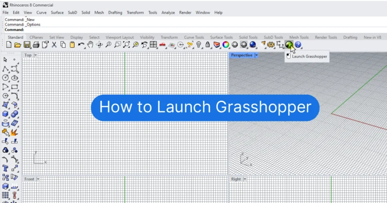
First things first, how can we add the Image Sampler component?
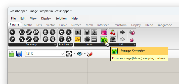
You can find the component in the ‘Params‘ component tab, under ‘Input‘.
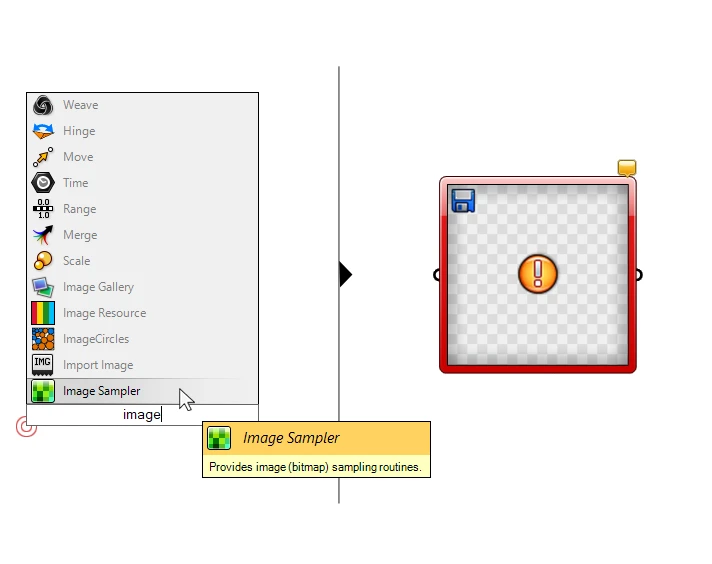
To add it through the component search bar, simply double-click on the spot on the canvas where you want the component to be placed and type: ‘image’.
Select the Image Sampler (with the green pixels icon) to drop it to the canvas.
How to Import an Image into the Image Sampler In Grasshopper
Now let’s get familiar with the component itself. Being an image sampler, the first thing it wants is an image to process! To add an image, double-click on the component.
The following Image Sampler Settings window will open:
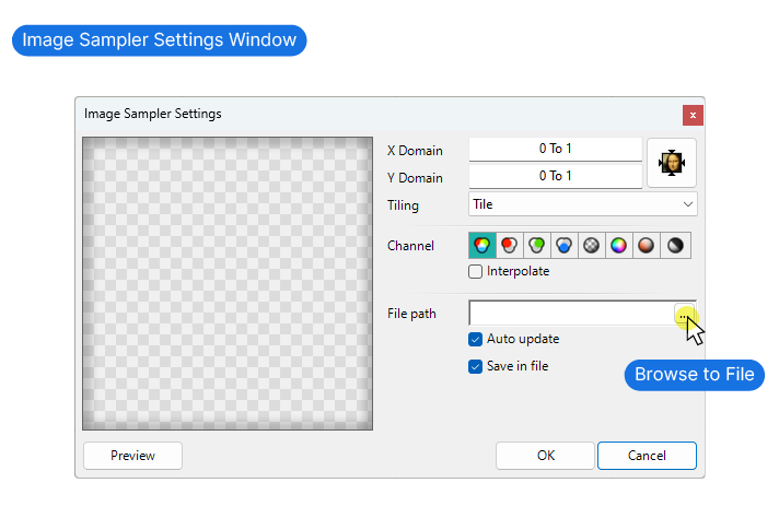
Click the three dots next to ‘file path’ on the right to browse and select your image. It can be any of the following filetypes:
- .bmp
- .jpeg
- .png
- .gif
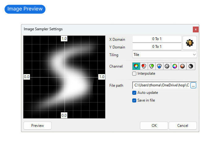
Once selected, the image will appear in the preview window of the Image Sampler Settings window.
Below the ‘file path’ field, we can choose to ‘Auto Update‘ the image and to ‘Save in file‘. They are both turned on by default, and I recommend to keep it that way. ‘Auto Update’ ensures that the linked image will be updated if you change the file on your drive. ‘Save in file’ means that the image is going to be saved inside the Grasshopper .ghx file. This is a life-saver believe me, you don’t want to have to keep track of where you saved that file.
Now in order to understand the other settings, we need to cover the basics of how the Image Sampler in Grasshopper works.
How the Image Sampler works
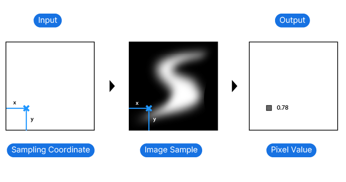
The core idea of the image sampler is best understood when considering its three main components: its input, the actual image, and the output.
The input is the sample coordinates. The purpose of the sample coordinates is to describe the location on our image to extract information from. The location is described in the form of coordinates: an x- and a y-value. And the output then contains the information of the image’s pixels at those locations.
Now in order to get predictable results, the crucial part is the sampling process. We need a way to map our sample coordinates to the image’s pixels.
For example, if our image is 100 x 100 pixels and we are trying to sample a pixel at coordinates 0, 300 we have a problem. Our sampling point is ‘out of bounds’.
So the key to the Image Sampler is to ensure that the ‘bounds’, or domains of our sample coordinates and our image match. So that if the image has a resolution of 100 x 100 pixels, our sample point coordinates can’t exceed the range of 0 to 100 in both the x and y direction.
In order to get a detailed and clear design from our image, we need to pick a lot of sample points, similar to increasing the resolution in an image. The more points we use, the more accurately our design will reflect the sampled image.
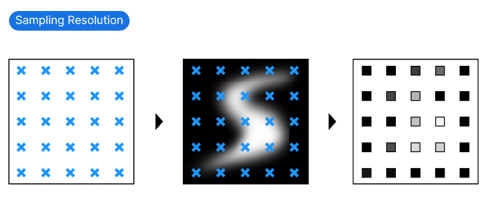
To evenly lay out the points on the image, creating a grid of sample points is the most common way. There are several methods to generate such sample point grids, for example by dividing a surface. More on that in the tutorial below.
But before that, let’s learn what the Image Sample outputs!
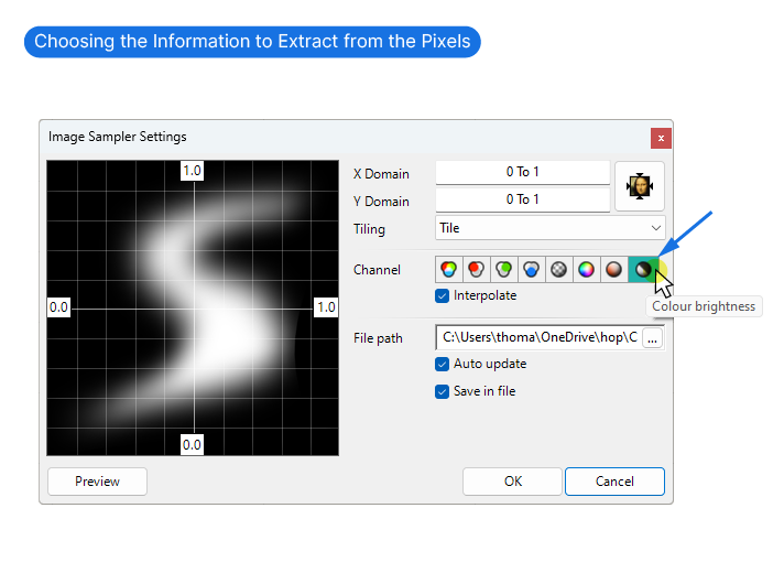
Channel Settings – Understanding the Image Sampler’s Outputs
With the ‘Channel‘ settings in the Image Sampler Options, we define which property of the pixel information we want to extract from the image.
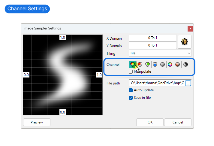
We can choose between the following:
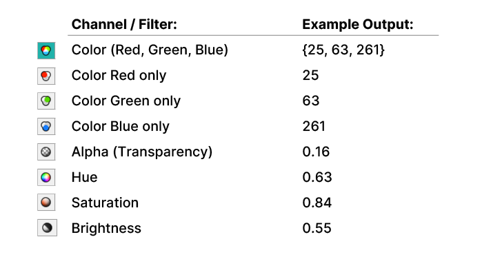
Any color can be presented with RGB values. RGB stands for the mix of Red, Green, and Blue that make up the color. If we sample the full RGB value, the Image Sampler returns all three of these values, like so:
   25, 63, 261
(Red, Green, Blue)
This is great when we want to use the image to color geometry in our script.
All the other channel or filter options extract one particular property of that color and return just a single number.
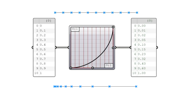
The Brightness channel for example, returns the brightness of any sampled pixel on the image as a number between 0 and 1.
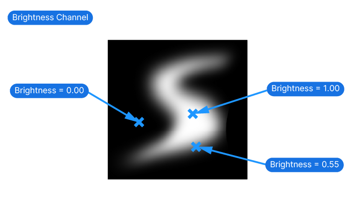
So if we have a black-and-white image, Black would be represented by 0, White by 1, and all the shades of gray between by decimal numbers, like 0.55.
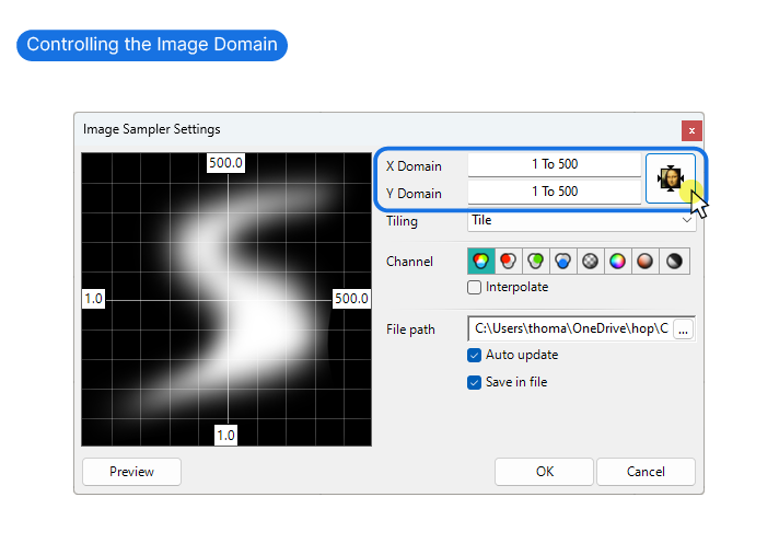
The Image Domain
In the the Image Sampler Settings window, the first two fields allow us to define the X and Y Domain.
Here we are telling Grasshopper how to describe locations on the image. With the default 0 to 1 values, it means that a sample coordinate of 0.50, 0.50 would return the value of the pixel in the center of the image.
We have the option of setting the domain to match the exact resolution of the image, by clicking the Mona-Lisa icon on the right of the Domains.
In doing so, if the image has a resolution of 500 by 500 pixels, the domain would be made to match and range from 1 to 500 in both axis.
The numbers on the preview image display the domain min and max values.
Whatever values we define for the domain, it’s crucial that our sample coordinates fall within the same numerical domains.
I recommend to use the domain of 0 to 1 for both the Image and the Sample Coordinates.
This may all sound a bit abstract, so let’s dive into a practical example!
Image Sampler Grasshopper Script – Step by Step Tutorial
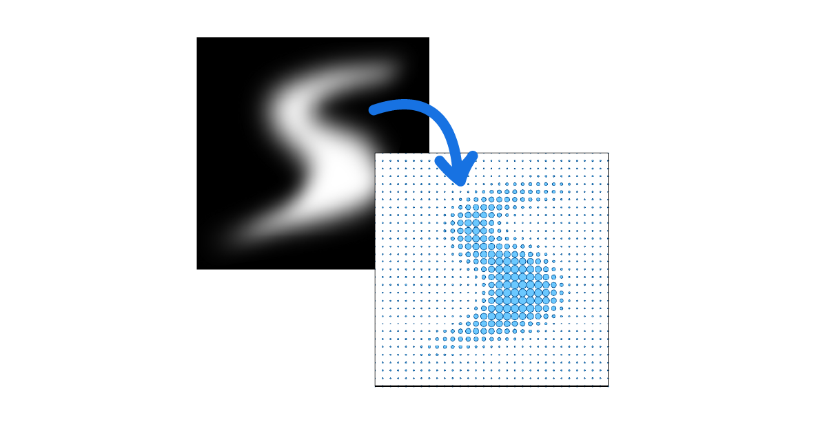
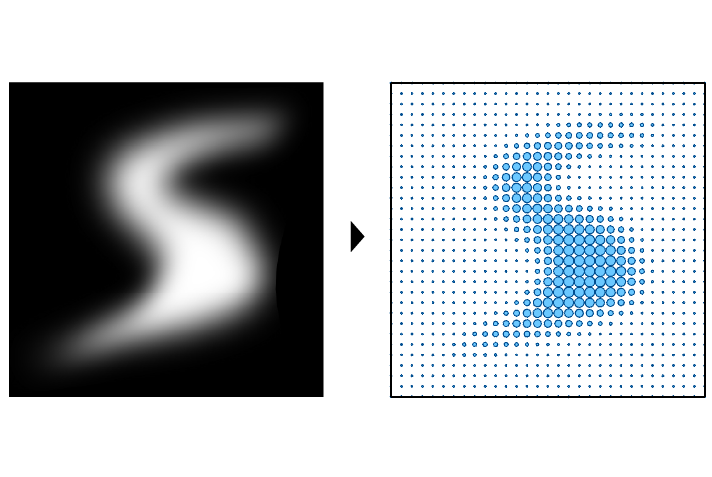
To give you a useful example, I’ll show you how to use the Image Sampler to create the effect shown below. We will create a grid of points on a surface and use the brightness of the image to control the size of the circles’ radius. Here is our final outcome:
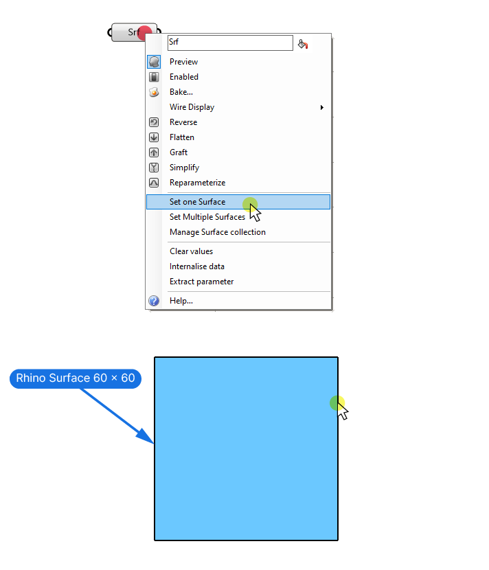
Step 1: Setting Up the Script
Let’s start by referencing a Surface from Rhino. We’re going to use a square image, so I’ll make the surface square as well. I’ll give it a size of 60 x 60 units.
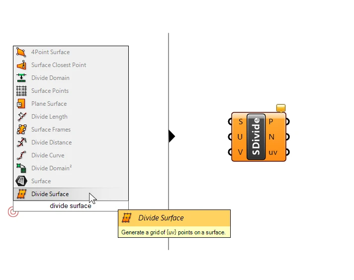
Step 2: Generating a Sampling Point Grid
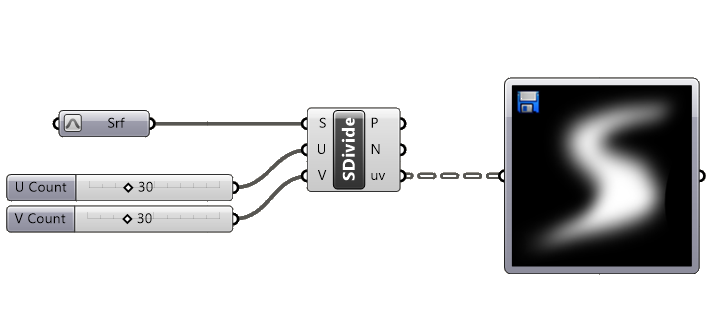
Now before we can use the Image Sampler, we need to generate our sample coordinates. Let’s go ahead and use the ‘Divide Surface’ component to create a grid of points on the surface.
Double-click onto the canvas and type ‘divide surface‘ into the component search bar, and select the first result to add it.
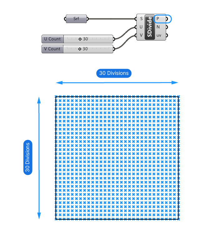
The Divide Surface component will take the Surface (S) input and ‘divide’ it into a grid of points. We can control the grid by defining the number of divisions in the U and V direction of the surface: U-Count (U) and V-Count (V). Let’s add two Number Sliders to do that.
Since the Surface is square, I’ll use the same value: 30. We can always come back and edit this later.
We get a grid of points on the surface, that are returned in the first output: Points (P).
Step 3: Generating Sample Coordinates
Now, the actual point output doesn’t qualify as sample points for the Image Sampler because the points are made up of three coordinates: the x, y, and z-value. Let’s take a look at the Point (P) output with a Panel component.
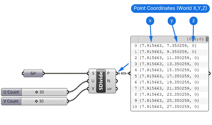
These coordinates reflect the points’ location in Rhino’s world coordinate system. The numbers will vary depending on the position of the surface we referenced, and on top of that, since the surface is 60 by 60 units, the coordinates definitely exceed the 0 to 1 range we need to stay within.
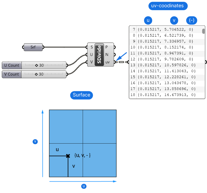
But the beauty of the Divide Surface component is that besides generating the grid of points, it also outputs the so-called uv-coordinates that define the points’ U and V location in relationship to the surface.
By default, the uv-domain of a surface will be made up of arbitrary numbers that roughly match the surface’s height and width. which explains why the numbers here also exceed our target domain of 0 to 1.
But here’s the good news: we can reset the surface’s uv-domain to be exactly between 0 and 1 in both the u-and v-direction!
Once we do that, any uv-coordinate the Divide Surface component returns, will also fall exactly into this domain!
Step 4: Adjusting the Sample Coordinates’ Domain
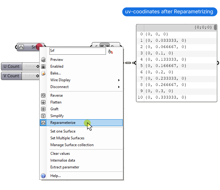
To set the UV-Domain to 0 to 1, we need to ‘reparametrize‘ the Surface.
Reparametrizing means that the Surface domain will be reset to a range of 0 to 1 in both the U and V direction. To reparametrize the surface, right-click on the Surface container component, and select ‘Reparametrize‘.
A quick check in the Panel shows that the numbers are now in the correct domain (0 to 1.00).
Time to sample the image!
Step 5: Preparing the Image Sampler
Let’s add the Image Sampler component.
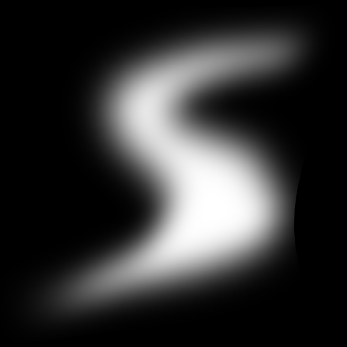
Let’s start by adding the image, by double-clicking on the Image Sampler and browsing to the image file. I created the image in Photoshop with a size of 500 by 500 pixels. The image will be square just like our sample point grid, which means we won’t get any distortion.
Feel free to save the image below and use it if you are working along!
Let’s also go ahead and connect the uv coordinates output to the Image Sampler input.
Next, let’s define which information we want to extract from each pixel. We want to control the size of circles with the image, so we only need to extract a single number from each pixel. Since our image is black and white, let’s use the brightness. The brightness will be 0 if the color is black, and 1 where it’s white.
To have the Image Sampler return the brightness of the sampled pixels, open the Image Sampler Settings by double-clicking on the component, and select the brightness channel on the far right.
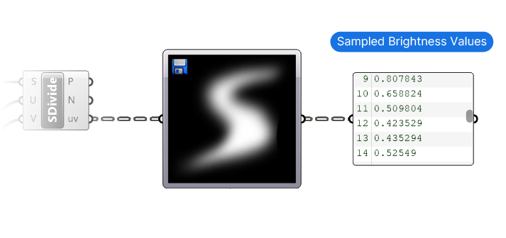
As a quick check with a Panel component confirms, we are getting simple numbers that reflect the brightness at the sampled coordinates.
We’ve got all the numbers figured out now, but where is our actual geometry? Time to add it!
Step 6: Transforming Geometry with Image Data
To keep the Grasshopper script simple, we’ll create circles centered on the point grid, and control the size of the circles with the Image Sampler output.
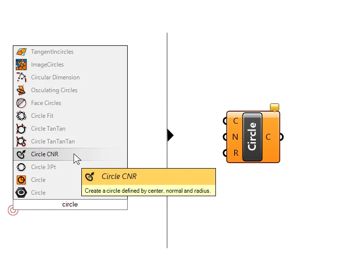
Let’s add a Circle component. There are several components to generate a circle in Grasshopper, in our case we want to be able to control the circle’s center and its radius, so let’s pick the Circle CNR (Circle) component. CNR stands for Center, Normal, and Radius – the three circle parameters we can define with this component!
The circles’ center points will be the point grid we generated with the help of the ‘Divide Surface’ component. Let’s go ahead and connect the Points (P) output to the Center (C) input.
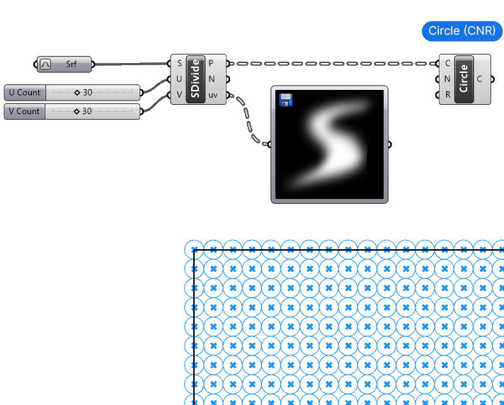
The Grasshopper preview now shows the circles around each grid point. The Circle (CNR) component comes with a default circle Radius (R) of 1, and all circles have that radius right now.
Since we’ve drawn a horizontal surface, we won’t need to specify a Normal (N) for the circle, as the default normal points along the z-direction already.
Now let’s connect the output of the Image Sampler component to the Radius (R) input of the Circle CNR component to have our script come to life!
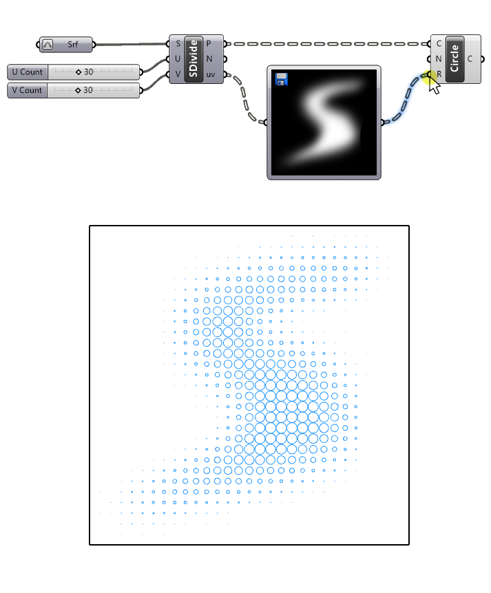
And just like magic our gradient image is now translated into a geometric gradient! Pretty awesome, right?
Step 7: Ensuring Geometrical Validity
Now currently we only see the circles that fall within the white part of the image, with the circles disappearing once they reach the black portion of our image. Since there the brightness is 0, the radius is also 0, which creates an invisible (and invalid ) circle.
Still, it would be nice to have some circles there as well. To fix that, we can define a minimum radius that each circle should have, a baseline circle size so to speak.
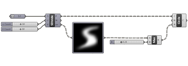
To do that we’re going to use a component called ‘Maximum (Max)’. You can find it in the ‘Math‘ component tab, all the way on the right grouped under ‘Util‘. Or just add it by searching ‘max’ in the component search bar.
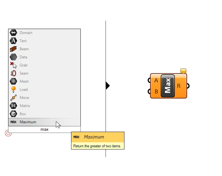
This component is straightforward: it has two inputs, number A and number B, and it returns whichever of the two numbers is larger – hence the name ‘Maximum’. (Grasshopper also has the opposite component, fittingly called ‘Minimum’.)
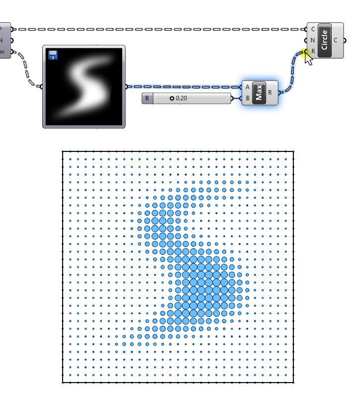
Now let’s connect the number output of the Image Sampler to the ‘A’ input, and a Number Slider with a value of 0.20 to the ‘B’ input.
And let’s connect the result to the circles’ Radius (R) input, replacing the previous wire connection.
Now all the numbers that were below 0.20 are ‘lifted’ to the value 0.20, which in turn means that all circles will at least have a radius of that size.
Step 8: Completing the Script
And there we have it!
We’ve successfully controlled a geometric transformation gradient with an image with the help of the Image Sampler!
Check below for the full script:
In our example, we used the brightness output values directly as our radius size. This means the circle radii vary from 0 to 1. In practice, we’ll want to be able to control the exact size, and we can do so by ‘remapping‘ the values to a domain of our choice. But that’s something for another time!
Conclusion: The Power of the Image Sampler in Grasshopper
Concluding, mastering the Image Sampler in Grasshopper is crucial if you aim to integrate complex gradients from images into your projects. The key to making this work is to ensure that the domain of the sample coordinates and image coordinates align.
If you’re looking to fast-track your Grasshopper skills, consider my Grasshopper Pro course. It’s designed specifically for professional architects, making learning Grasshopper faster and more efficient. Take this opportunity to unlock advanced parametric design techniques and elevate your architectural designs with Grasshopper Pro!
Happy designing!